3 - 23
Upper shaft mechanism
Main unit
Assembly
11
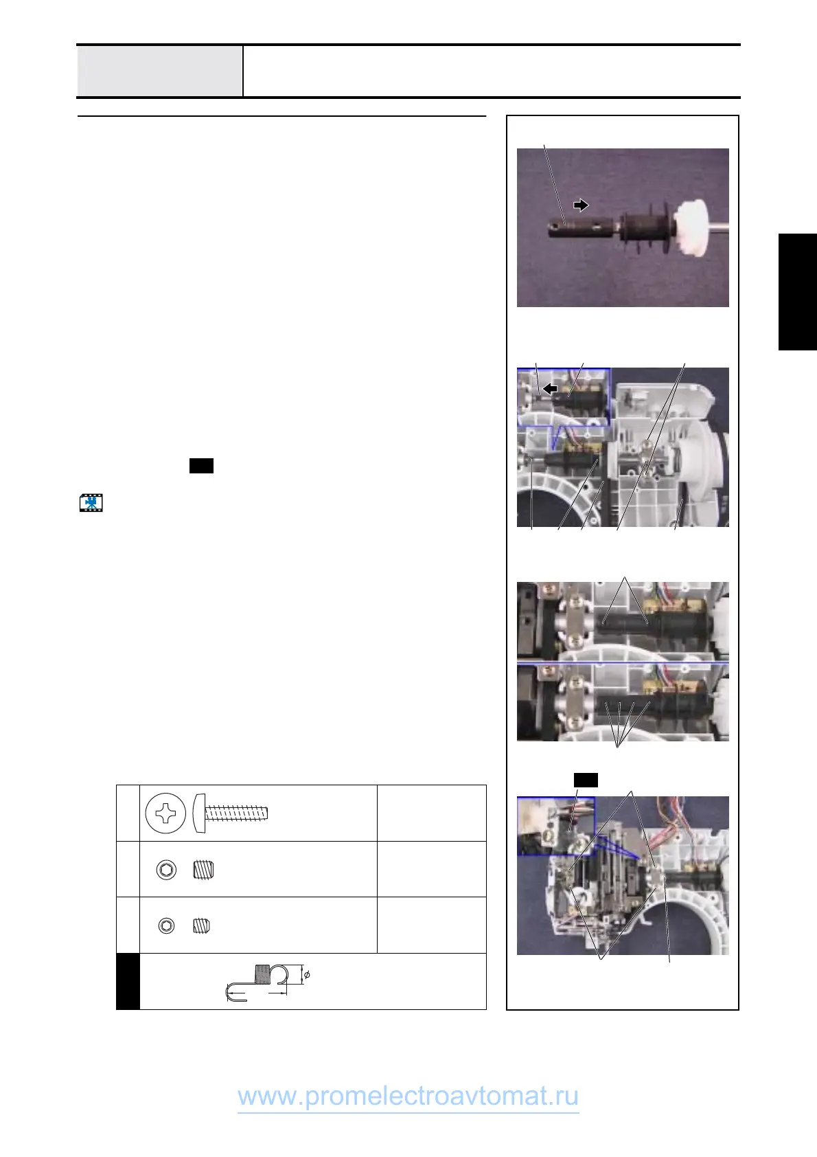
Upper shaft assy. attachment
1. Attach the fixed joint 1 to the upper shaft assy., and move it toward the
timing shutter side.
*Key point
• Approximately half of the fixed joint 1 is hidden by the timing
shutter.
• The screw holes in the fixed joint 1 are offset to the left.
2. Attach the upper shaft assy., timing belt (motor) 2 and timing belt (rotary
hook drive) 3 to the arm bed.
3. Attach the upper shaft bearing presser 4 to the arm bed using screws 1
(two).
4. Slide the fixed joint 1 onto the unit shaft 5 (needle-presser module), and
attach it using screws 2 (set screw, socket (FT) M5X5) (two) and screws
3 (set screw, socket (CP) M4X4) (four).
*Key point
• Align the timing shutter base line 6 and the unit shaft D cut
7.
• The gap (8) between the fixed joint and the needle presser
module is approximately 0.5 mm.
5. Fully tighten screws 4 (four), which were hand started in 3 - 21" 8
Needle-presser module attachment."
6. Attach spring to the thread hook assy. and the upper shaft bushing
presser.
Start movie clip (CD-ROM version only)
1
2
Torque
1.18 - 1.57 N-m
2
Torque
1.18 - 1.57 N-m
3
Torque
0.78 - 1.18 N-m
S38
1
4
4
5 1
43 2
Approximately half hidden
2
3
8
Approx. 0.5mm
67
S38
S38
Giza Tite
5X16
Color; Gold
Set Screw, Socket (FT)
M5X5
Color; Black
Set Screw, Socket (CP
M4X4
Color; Black
SPRING
XA5246***
15.3
5
www.promelectroavtomat.ru
 Loading...