3 - 24
Upper shaft mechanism
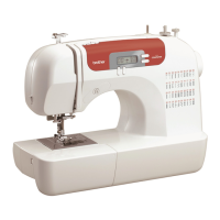
Main unit
12
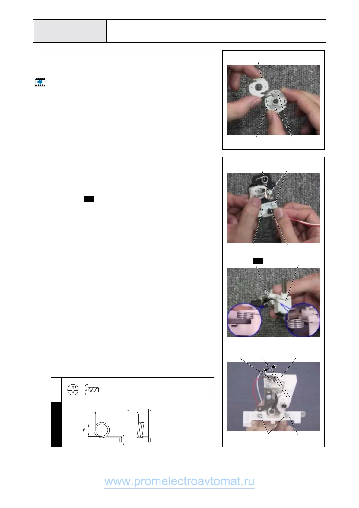
Bobbin base assembly
1. Attach the NT lower thread cutters 2 (two) and the bobbin thread cutter
holder 3 to the bobbin base 1.
Start movie clip (CD-ROM version only)
3
21
13
Bobbin winder assy. assembly
1. Attach the BWSW-S assy. 1 to the SW adjust plate 2.
2. Attach the SW adjust plate 2 and the bobbin winder shaft stopper 3 to
the bobbin winder assy. holder using screws 1 (two).
3. Attach the BW shaft holder assy. to the bobbin winder assembly holder.
4. Attach spring to the BW shaft holder assy. 4 and bobbin winder
assy. holder.
5. Attach the Board presser 5 using screws 2 (two).
*Key point
• With bobbin winding OFF, adjust the position of 2 so that the
gap between the 1 BWSW-S assy. and the BW shaft holder
assy. 4 is 2.5 ± 0.3 mm.
1
2
Torque
0.57 – 0.78 N-m
S21
3 1
12
S21
4
52
2.5 ±0.3mm
41
S21
Screw, Bind
M3X6
Color; Silver
BOBBIN WINDER SPRING
XZ0070***
7.1
2.5
4 4 2.8
www.promelectroavtomat.ru
 Loading...