3-4
Confidential
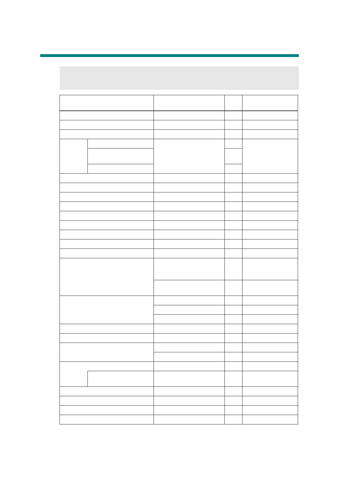
4. SCREW TORQUE LIST
Note:
• For verifying the shape of each screw, refer to "3.SCREW CATALOGUE" in this chapter.
Location of screw Screw type Q'ty
Tightening torque
N.m (kgf.cm)
T1 tray cover Taptite bind B M4x12 2 0.8±0.1(8±1)
Side cover L Taptite cup B M4x12 2 0.8±0.1(8±1)
Side cover R Taptite cup B M4x12 2 0.8±0.1(8±1)
Main
shield
cover
plate
HL-5440D
Taptite cup S M3x8 SR
0
0.5±0.1(5±1)
HL-5450DN/5450DNT/
5470DW/5470DWT
4
HL-6180DW/6180DWT 3
Top cover ASSY Taptite cup B M4x12 2 0.8±0.1(8±1)
Panel PCB ASSY (LED model) Taptite pan B M3x8 3 0.4±0.05(4±0.5)
Top cover Taptite cup B M4x12 4 0.8±0.1(8±1)
Fuser unit line cover R Taptite bind B M4x12 1 0.8±0.1(8±1)
Fuser unit line cover L Taptite pan B M4x14 1 0.8±0.1(8±1)
Fuser unit Taptite pan B M4x14 1 0.8±0.1(8±1)
Main PCB ASSY Taptite cup S M3x8 SR 4 0.5±0.1(5±1)
Parallel interface (HL-5440D only) Screw pan M3x6 2 0.5±0.1(5±1)
Laser unit Taptite cup S M3x8 SR 4 0.8±0.05(8±0.5)
Scanner earth plate
Taptite cup S M3x8 SR
(Fastening side of
scanner
plate
)
10.8±0.1(8±1)
Taptite cup S M3x8 SR
(LV shield plate side)
10.5±0.1(5±1)
LV shield plate cover
Taptite cup S M3x8 SR 3 0.5±0.1(5±1)
Taptite bind B M4x12 1 0.8±0.1(8±1)
Screw pan M4x8 1 0.5±0.1(5±1)
Inlet Taptite flat B M3x10 1 0.5±0.1(5±1)
FG harness Screw pan M4x8 1 0.5±0.1(5±1)
Low-voltage power supply PCB
ASSY
Taptite cup S M3x8 SR 1 0.5±0.1(5±1)
Taptite bind B M4x12 2 0.8±0.1(8±1)
Under bar earth plate R Taptite cup S M3x8 SR 1 0.5±0.1(5±1)
Under bar
(Front right side)
Taptite bind B M4x12 1 0.8±0.1(8±1)
LV shield plate Taptite bind B M4x12 1 0.8±0.1(8±1)
Hold cover 1 Taptite bind B M4x12 1 0.8±0.1(8±1)
Toner LED PCB ASSY Taptite pan B M3x8 1 0.5±0.1(5±1)
Hold cover 2 Taptite bind B M4x12 2 0.8±0.1(8±1)
 Loading...