3-26
Confidential
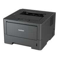
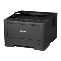
9.10 Control panel
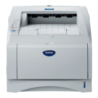
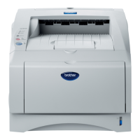
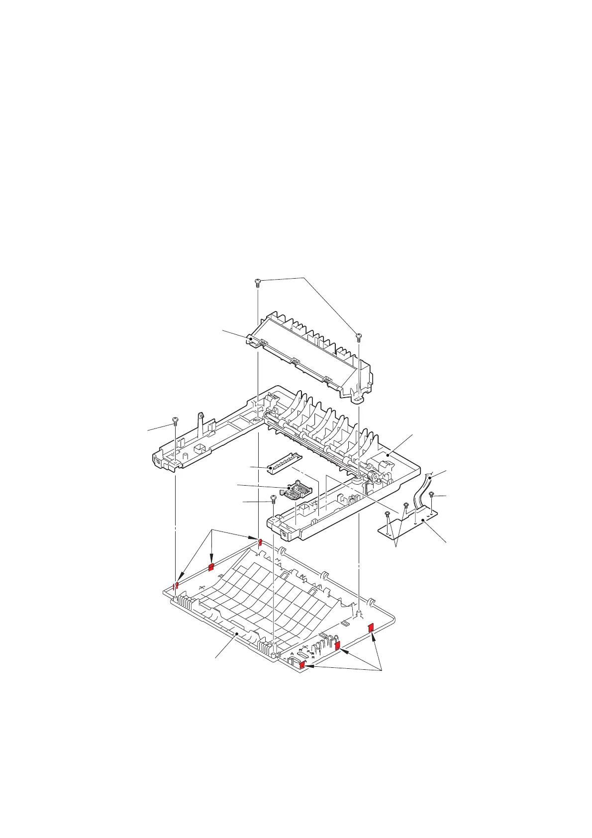
LED model
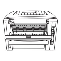
(1) Release the panel harness from the securing fixtures.
(2) Remove the three taptite pan B M3x8 screws, and remove the panel PCB ASSY from
the top cover ASSY.
(3) Remove the panel light guide from the top cover ASSY.
(4) Remove the SW key printed ASSY from the top cover ASSY.
(5) Remove the two taptite bind B M4x12 screws "a", and remove the inner chute ASSY
from the top cover ASSY.
(6) Remove the two taptite bind B M4x12 screws "b", release the six hooks, and remove the
top cover base from the top cover ASSY.
Fig. 3-24
Harness routing: Refer to “1.Main PCB ASSY”.
Taptite bind B M4x12 screws “a”
Inner chute ASSY
Hooks
Top cover ASSY
Top cover base
Taptite pan
B M3x8
Panel PCB ASSY
Hooks
Taptite bind B
M4x12 screws “b”
Taptite bind B
M4x12 screws “b”
SW key
printed ASSY
Panel light
guide
Panel harness
Taptite pan
B M3x8
 Loading...