3 - 18
Thread tension unit
Main unit
Assembly
Assembly
10
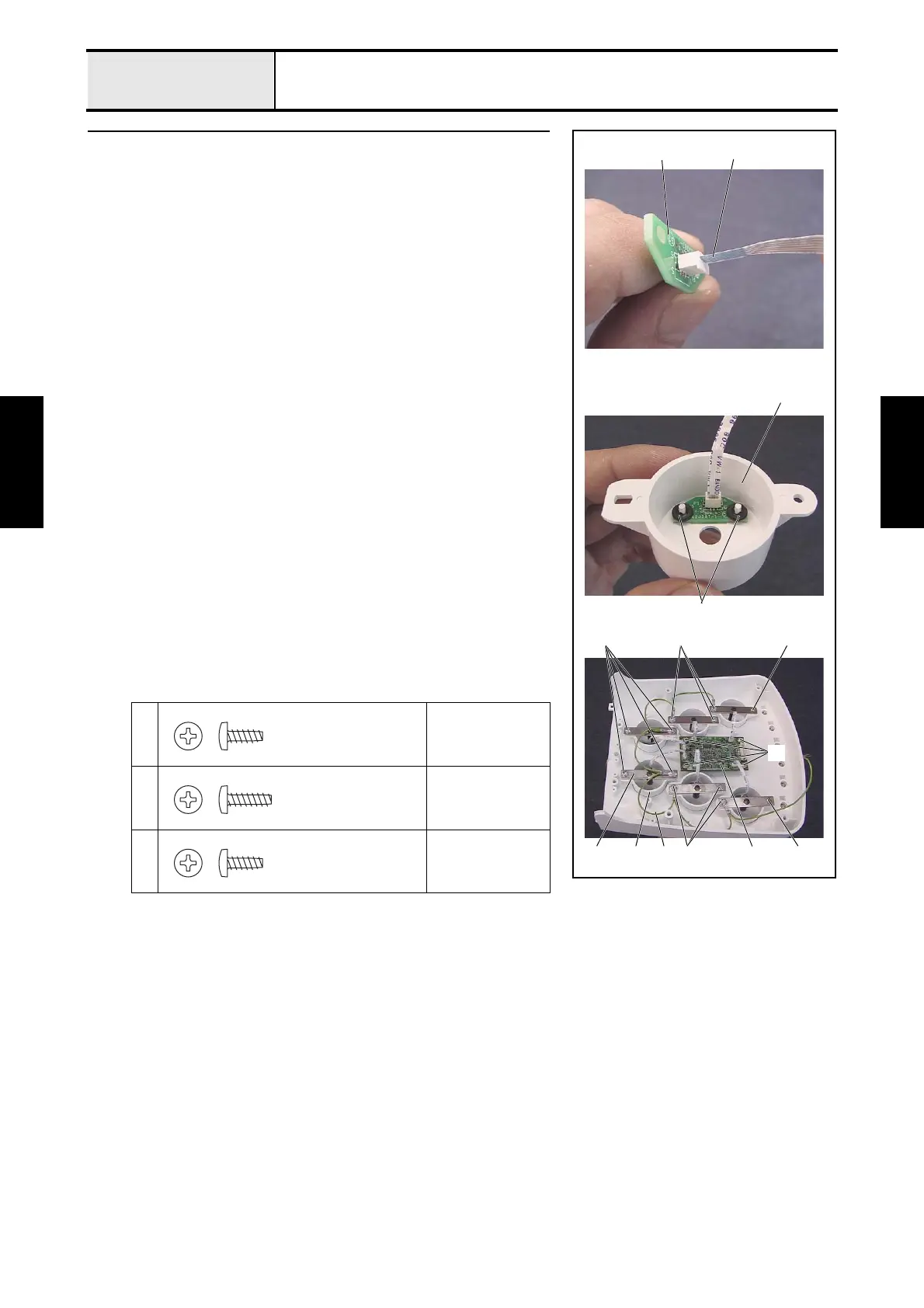
Thread sensor assembly and head PCB assembly attachment
1. Connect the FFC (SML2CD-H) 2 to the thread sensor assembly 1. (6
locations)
*Key point
• Connect the FFC (SML2CD-H) so that the blue surface is
facing the thicker portion of the thread sensor assembly's
connector.
2. Attach the thread sensor assembly 1 and the 2 rubber washers to the
thread quantity sensor cover 3, and then attach the 2 retaining rings CS2.
(6 sets)
3. Attach the thread tension bracket assembly 4, thread quantity sensor
cover assembly 5, and head grounding wire assembly 6 to the tension
base assembly with the 2 screws 1 and the 10 screws 2. (6 locations)
*Key point
• Tighten the head grounding wire assembly together with the
thread tension bracket assembly. (6 locations)
4. Attach the head PCB assembly 7 to the tension base assembly with the 4
screws 3, and then connect the 6 FFCs (SML2CD-H) to the head PCB
assembly.
*Key point
• Connect the FFC (SML2CD-H) so that the blue surface is
facing the thicker side of the head PCB assembly's connector.
1
Torque
0.59 — 0.78 N-m
2
Torque
0.59 — 0.78 N-m
3
Torque
0.59 — 0.78 N-m
12
Retaining rings CS2
3
1
5 7
2
4 6
3
2
2 1
Taptite, Bind B
M3X8
Taptite, Bind B
M3X10
Taptite, Bind B
M3X8