4 - 18
Inspection and
Adjustment
Inspection and
Adjustment
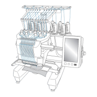
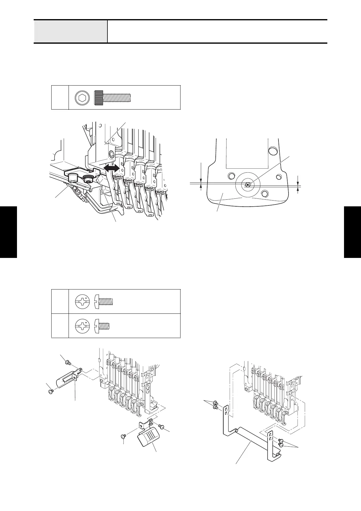
Adjustment Needle drop (front/back)
6. Loosen the screw 3 of the case positioning plate on the lower section of the needle bar case unit.
7. Move the case positioning plate to either the front or back to adjust the needle front/back position.
8. Tighten the screw 3 of the case positioning plate on the lower section of the needle bar case unit to secure the
case positioning plate.
9. Check the front/back (needle drop) for all other needle bars using these same steps.
10. Attach the 4 screws 2 to secure the thread presser base assembly.
*Key point
• When securing the thread presser base assembly, make adjustments following the guidelines in section “4-
34 Thread presser base up/down position”.
11. Attach the 4 screws 1 to secure the LED unit right assy and the LED unit left assy.
3
1
2
Bolt, Socket
M5X16
Needle tip
more than
0.3 mm
more than
0.3 mm
Case positioning plate
with hex wrench
4 mm
3
Needle plate
Needle bar case unit
Screw, Bind
M4X8
Screw, Bind
M4X6
2
2
Thread presser base assembly
LED unit left assy
LED unit right assy
1
1
1
1

 Loading...