2 - 23
Feed unit
Main unit
Disassembly
Disassembly
12
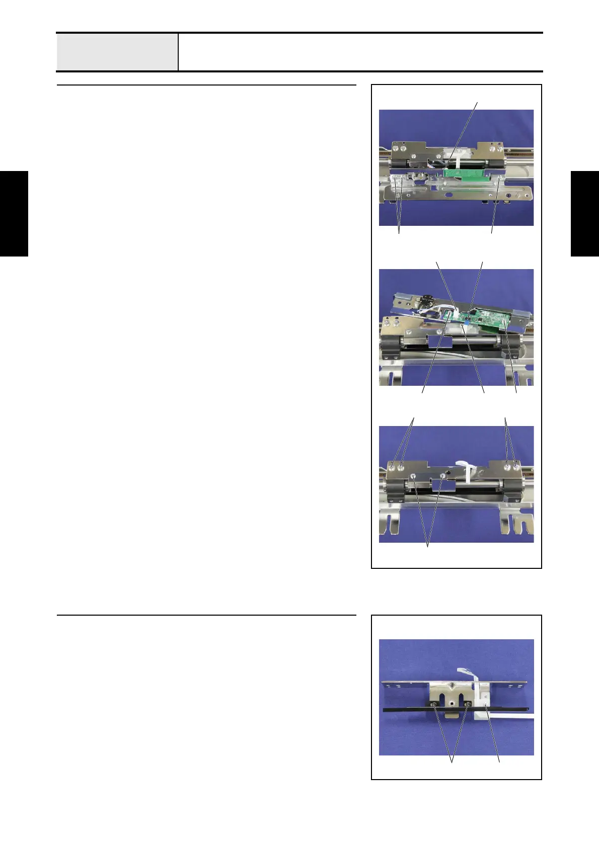
X-carriage A assembly and X-carriage B assembly removal
1. Remove the 3 screws 1, and then remove the hoop sensor assembly's lead
wire connector 1 from the hoop PCB assembly while removing the X-
carriage A assembly.
2. Unlock the hoop PCB assembly's FFC (SML2CD-X) connector 2.
3. Disconnect the FFC (SML2CD-X) from the hoop PCB assembly, and then
remove the screw 2 and the sheet.
4. Remove the 2 screws 3, and then remove the hoop PCB assembly.
5. Remove the 2 screws 4, and then remove the X carriage DX.
6. Remove the 4 screws 5, and then remove the X-carriage B assembly.
1
1 1
2
5 5
1
3 3
2
4
13 X-sensor dog removal
1. Remove the screw 1, and then remove the sheet and disconnect the FFC
(SML2CD-X).
2. Remove the 2 screws 2, and then remove the X-sensor dog.
2 1
 Loading...