2002 Buell X1: Chassis 2-43
HOME
ASSEMBLY/INSTALLATION
1. See
Figure 2-67. If removed, install new bearing cups
into frame steering head using
STEERING HEAD
BEARING RACE INSTALLER (Part No. HD-39302).
2. See
Figure 2-66. Liberally coat the bearing cones (4)
with grease using WHEEL BEARING PACKER TOOL
(Part No. HD-33067). Work the grease into the rollers.
3. Install lower bearing.
a. Place lower bearing dust shield (3) over fork stem.
b. Find a section of pipe having an inside diameter
slightly larger than the outside diameter of the fork
stem.
c. Press bearing (4) with small end up onto fork stem
and lower triple clamp (6). Use the pipe as a press-
on tool.
4. Insert lower triple clamp (6) through the steering head.
Install the upper bearing (4) with small end down and
dust shield (3) onto fork stem.
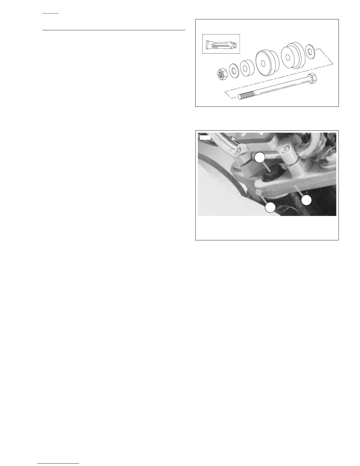
5. See
Figure 2-68. Apply LOCTITE ANTI-SEIZE to fork
stem bolt (1). Loosely install upper triple clamp (2) using
fork stem bolt.
6. Install fork assemblies. See 2.16 FRONT FORK.
7. Install steering head lock. See
2.18 STEERING HEAD
LOCK.
8. Install instrument support and handlebars. See
2.26
INSTRUMENT SUPPORT
.
9. Check adjustment.
a. Tighten fork stem bolt (1). Check bearing adjust-
ment to set fork stem bolt to proper tension. See
1.17 STEERING HEAD BEARINGS.
b. Make sure the fork stem turns freely, then tighten
the fork stem clamp screw (3).
Figure 2-67. Steering Head Bearing Race Installer
Figure 2-68. Fork Stem Clamp Screw
 Loading...


