3-10 2002 Buell X1: Engine
HOME
INSTALLING THE ENGINE 3.4
ENGINE CRANKCASE
INSTALLATION
1. See
Figure 3-2. Place engine crankcase on supports so
frame may be installed over the top of the engine.
2. See
Figure 3-3. If removed, attach swingarm mount
block to engine. Install upper bolts (3), washers and lock-
nuts finger tight. Install lower bolts (4), washers and lock-
nuts finger tight. Tighten upper bolts to 41-45 ft-lbs (56-
61 Nm) and lower bolts to 68-75 ft-lbs (92-102 Nm).
3. If removed, install swingarm. Adjust swingarm bearing
preload. See
2.19 SWINGARM.
4. If removed, install transmission mainshaft sprocket. See
6.13 TRANSMISSION INSTALLATION AND SHIFTER
PAWL ADJUSTMENT
.
5. Remove oil filter (if installed). Walk frame over powertrain.
6. See
Figure 3-4. Attach front isolator (8). Install front iso-
lator mount with bolt (6), washers (7), D-washer (9) and
locknut (10). Flat on D-washer faces steering neck.
Tighten bolt finger tight.
CAUTION
Isolator bolts must be tightened within 30 minutes of
applying LOCTITE THREADLOCKER. Failure to tighten
bolts within 30 minutes may cause LOCTITE to set.
7. See
2.20 REAR ISOLATORS for installation. Apply LOC-
TITE ANTI-SIEZE under two isolator bolt heads. Install
rear isolators but do not tighten isolator bolts at this time.
CAUTION
Do not adjust tie bar assemblies. Tie bar tension is set at
the factory. Any attempt at adjusting tension will cause
damage to tie bars. Damaged tie bars must be replaced.
8. Rear tie bar must be horizontal and below frame tab.
Insert bolt upwards through washer, tie bar and frame.
Fasten with nut. Tighten bolt to 30-33 ft-lbs (41-45 Nm).
NOTE
See
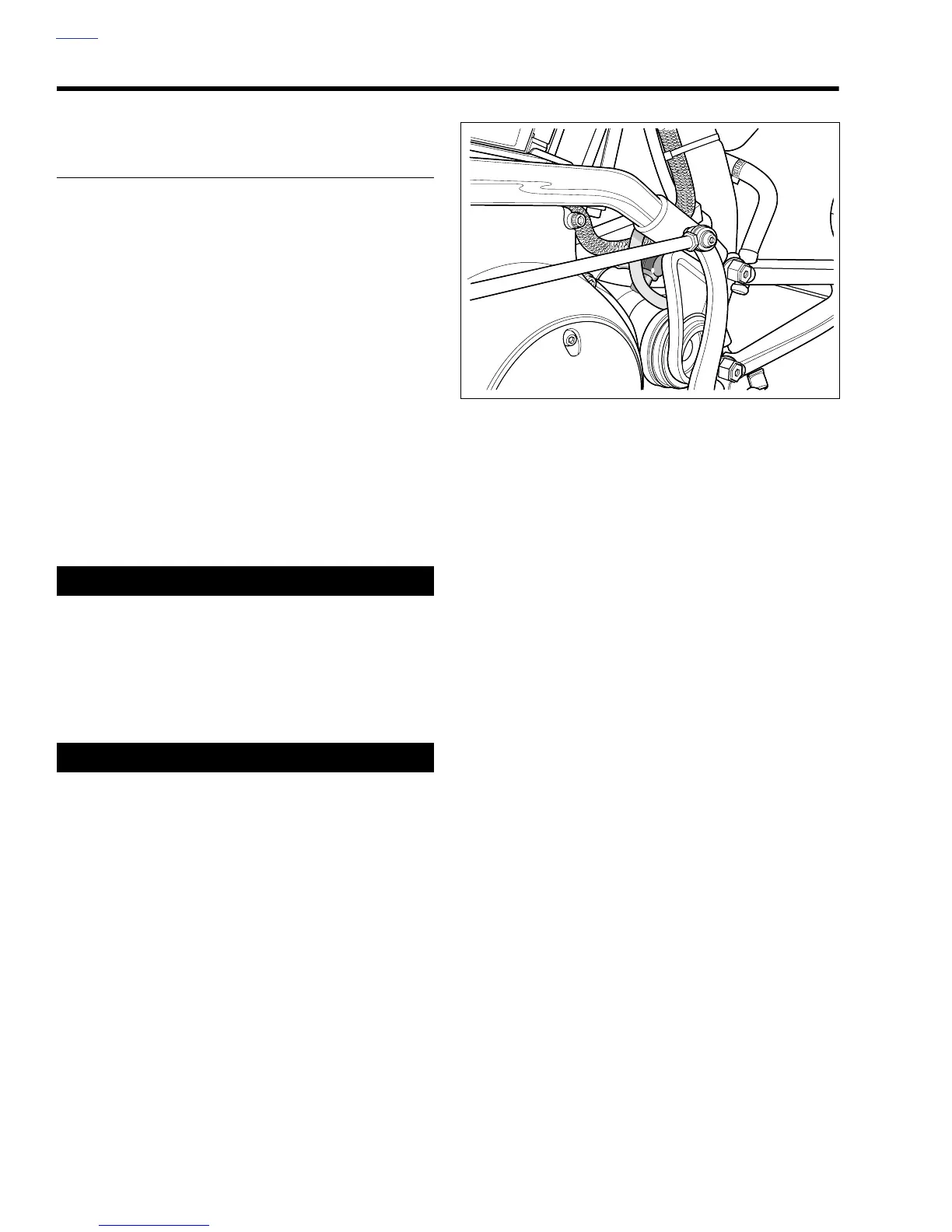
Figure 3-5. Route wire harness above rear tie bar, but
below rear brake line.
9. See Figure 3-4. Place clutch cable clamp (3) on front tie
bar bolt (2). Clamp should hold cable on primary cover
side of motor. Insert bolt from front through frame and
install washer (4). Continue through tie bar (1) and
frame. Install locknut (5) and tighten to 30-33 ft-lbs (41-
45 Nm).
10. Attach front upper tie bar (11). Insert bolt through tie bar
front isolator, and frame. Secure with nut and washer.
Tighten to 30-33 ft-lbs (41-45 Nm).
11. See
Figure 3-3. Tighten the two rear isolator TORX bolts
(7) to 63-70 ft-lbs (85-95 Nm). Make sure isolators do not
twist during tightening. See
2.20 REAR ISOLATORS.
12. See Figure 3-4. Tighten front isolator bolt (6) to 100-110
ft-lbs (136-149 Nm).
13. Connect hoses to oil tank. See 3.8 OIL HOSE ROUT-
ING. Use new hose clamps.
14. Attach battery ground strap to swingarm mount block.
15. Attach clutch cable to handlebar lever.
16. Remove strap from between engine cylinders. Using a
floor hoist, lift motorcycle by the frame and remove the
wooden cradle from underneath the crankcase.
17. Install rear shock. See
2.21 REAR SHOCK ABSORBER.
18. Install rear wheel and drive belt. See 2.6 REAR WHEEL.
After rear wheel and belt are installed, remove floor hoist
straps.
19. Install rear brake caliper. See 2.14 REAR BRAKE CALI-
PER
.
20. Attach disconnected wires. See Section 7.
a. Connect solenoid wire, circuit breaker charging wire
and battery positive cable to starter.
b. Connect voltage regulator connector to alternator
stator wiring.
c. Attach cam position sensor to wire harness.
d. Connect neutral switch wire to crankcase.
e. Attach oil pressure indicator switch wire.
21. Install rear fender and lower belt guard. See
2.32 REAR
FENDER
.
22. Install sprocket cover. See
2.30 SPROCKET COVER.
23. Install footrests. See
2.29 FOOTRESTS.
24. Continue with the steps listed under
ENGINE INSTALLA-
TION AFTER CYLINDER HEAD REPAIR.
Figure 3-5. Wire Harness Routing
b0761x1x









 To Next Page