6-6 2002 Buell X1: Drive/Transmission
HOME
DRIVE BELT 6.3
GENERAL
The drive belt should be checked for unusual wear, cracking
or loss of teeth. Check the belt sprocket for unusual wear,
broken teeth or damaged flange.
● See
1.11 DRIVE BELT DEFLECTION for adjustment
information.
● See
1.12 DRIVE BELT AND SPROCKET for inspection
and cleaning procedures.
REMOVAL
Belt removal requires special lifts to support the motorcycle. If
you do not have the proper equipment, have your Buell dealer
perform the repair.
1. Lift and secure the motorcycle.
a. Place vehicle on a lift and anchor front wheel in
place.
b. Raise rear wheel off lift using
REAR WHEEL SUP-
PORT STAND (Part No. B-41174).
1WARNING1WARNING
To protect against shock and accidental start-up of vehi-
cle, disconnect the negative battery cable before pro-
ceeding. Inadequate safety precautions could result in
death or serious injury.
2. Disconnect negative battery cable.
3. Remove the stone guard and lower belt guard. See
2.33
BELT GUARDS.
4. Remove chin fairing. See
2.34 CHIN FAIRING
5. Remove sprocket cover. See 2.30 SPROCKET COVER.
6. Remove rear fender. See
2.32 REAR FENDER.
7. See
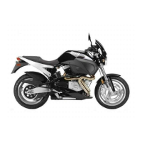
Figure 6-6. Remove rear wheel.
a. Remove rear axle nut (1) (metric), lockwasher (2),
washer (3) and right side axle carrier (4).
b. Hold axle adjuster bolt (5) with a 5/16 in. wrench.
Loosen locknut (6) and axle adjusters (7). Repeat
on left side.
c. From left side, slowly pull rear axle from swingarm.
As axle is removed, remove right side spacer, rear
brake caliper mount, left side axle carrier and
washer. Suspend rear brake caliper mount from
frame with a piece of rope. Push rear wheel forward
and slip off belt.
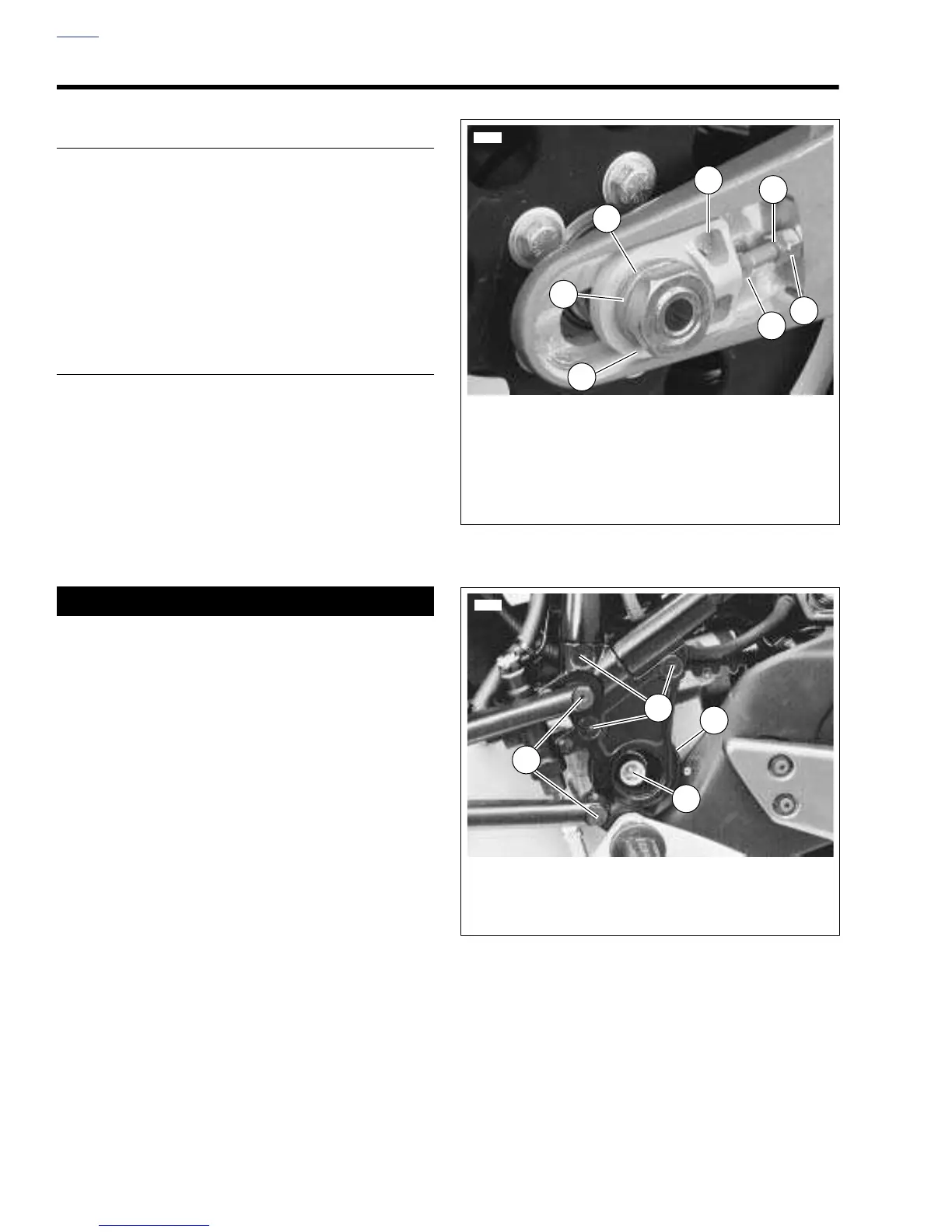
8. See
Figure 6-7. Remove right isolator TORX bolt (1) and
and isolator (3). See 2.20 REAR ISOLATORS.
9. Remove right side passenger peg mounting bolts (4).
10. Remove the three allen screws and nuts (2) from the
sideplate. Detach the sideplate using special care to
watch how the rear brake line is twisted.
11. Slide the drive belt from the sprockets between the frame
and mount block.
12. Inspect belt and sprockets. See
1.12 DRIVE BELT AND
SPROCKET.
Figure 6-6. Rear Axle, Right Side
Figure 6-7. Sideplate (Typical)
6851
2
4
3
1
6
5
7
1. Axle Nut
2. Lockwasher
3. Washer
4. Axle Carrier
5. Adjuster Bolt
6. Locknut
7. Adjuster
6880
2
1
1. Isolator Bolt (Typical)
2. Sideplate Screws and Nuts (3)
3. Rubber Isolator (Typical)
4. Passenger Footrest Mounting Bolts (2)
3
4