2-70 2002 Buell X1: Chassis
HOME
SPROCKET COVER 2.30
REMOVAL/DISASSEMBLY
1. See
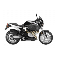
Figure 2-112. Remove two bolts (1), washers (2)
and rubber washers (3) from right side of chin fairing (4).
2. See
Figure 2-113. Remove nut and washer.
3. Remove sprocket cover screw, washer and spacer.
4. Remove swingarm drive/support and sprocket cover as
an assembly.
5. Remove two screws to separate sprocket cover from
swingarm/drive support. Do not remove rivet holding rub-
ber bumper.
ASSEMBLY/INSTALLATION
1. See
Figure 2-113. If removed, attach sprocket cover to
swingarm/drive support.
a. Place sprocket cover behind swingarm/drive sup-
port. Align holes in cover with holes in support.
b. Apply LOCTITE THREADLOCKER 222 (purple) to
both screws.
c. Install screws to rear of sprocket cover. Tighten
screws to 12-17 in-lbs (1-2 Nm).
2. Apply LOCTITE THREADLOCKER 243 (blue) to screw.
Install sprocket cover assembly with screw, washer and
spacer. Tighten screw to 48-72 in-lbs (5-9 Nm).
3. See
Figure 2-112. Apply LOCTITE THREADLOCKER
243 (blue) to bolts (1). Place metal washers (2) over
bolts (1) and then install rubber washer (3). Install bolts
(1) and tighten to 9-10 ft-lbs (12-14 Nm).
4. Install nut and washer to swingarm/drive support.
Tighten nut to 30-35 ft-lbs (41-47 Nm).
Figure 2-112. Chin Fairing, Right Side
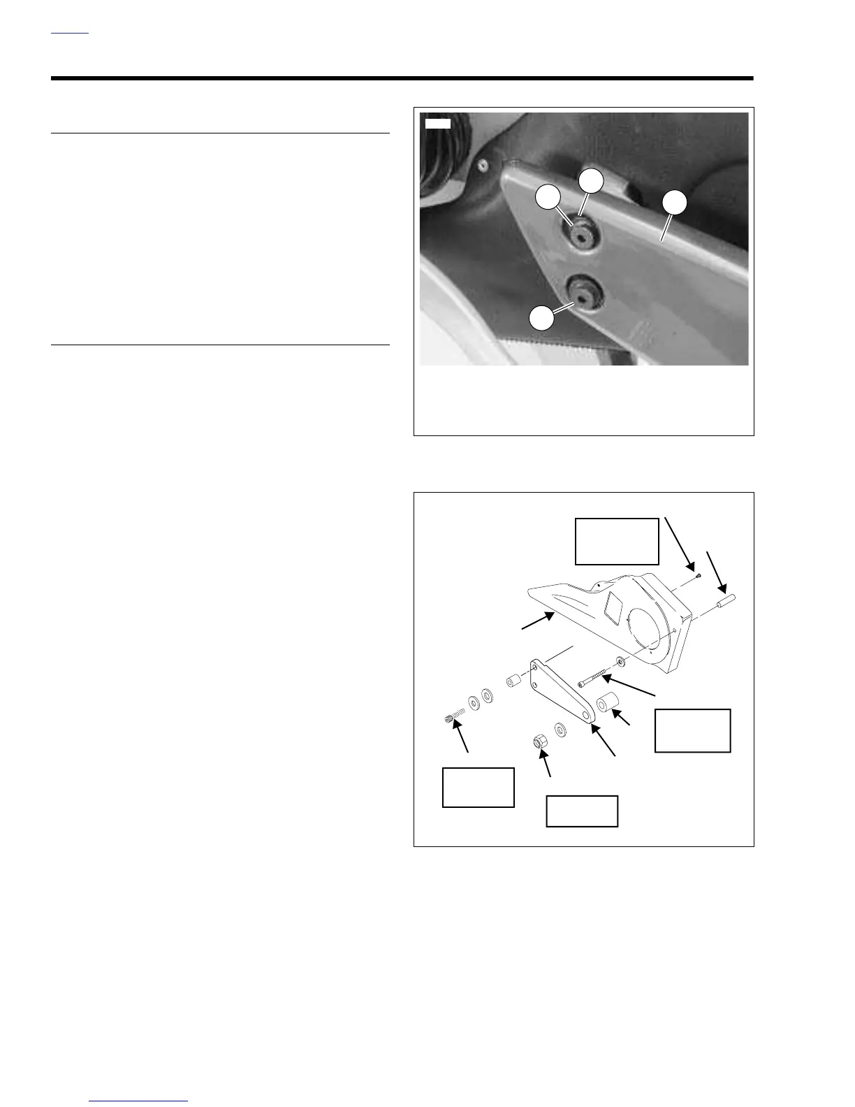
Figure 2-113. Sprocket Cover
1. Bolts
2. Washer
3. Rubber Washer
4. Chin Fairing
6986
1
2
3
4
b0204x2a
20-25 ft-lbs
(27-34 Nm)
Screws (2)
Locknut
30-35 ft-lbs
(41-47 Nm)
Swingarm/Drive
Support
Red Loctite
Screw
48-72 in-lbs
(5-9 Nm)
Blue Loctite
Screws (2)
Spacer
Sprocket
Cover
12-17 in-lbs
(1-2 Nm)
Purple Loctite
Spacer