2002 Buell X1: Fuel System 4-109
HOME
THROTTLE BODY AND INTAKE MANIFOLD 4.41
GENERAL
See
Figure 4-100. The throttle body and intake manifold con-
sist of the following components:
● Fuel injectors (front and rear).
● Fuel supply fitting.
● Idle speed adjustment screw.
● Cable bracket.
● Throttle position sensor.
● Throttle lever.
REMOVAL
The gasoline in the fuel supply line downstream of the
fuel pump is under high pressure (49 psi [338 kPa]). To
avoid an uncontrolled discharge or spray of gasoline,
always purge the system of high pressure gas before
removing fuel tank. Gasoline is extremely flammable and
highly explosive. Inadequate safety precautions could
result in death or serious injury.
1. Purge fuel line and remove fuel tank. See
4.37 FUEL
TANK.
2. Remove air cleaner cover and backplate. See 4.42 AIR
CLEANER
.
3. See
Figure 4-100. On California models, pull EVAP hose
from fitting (3).
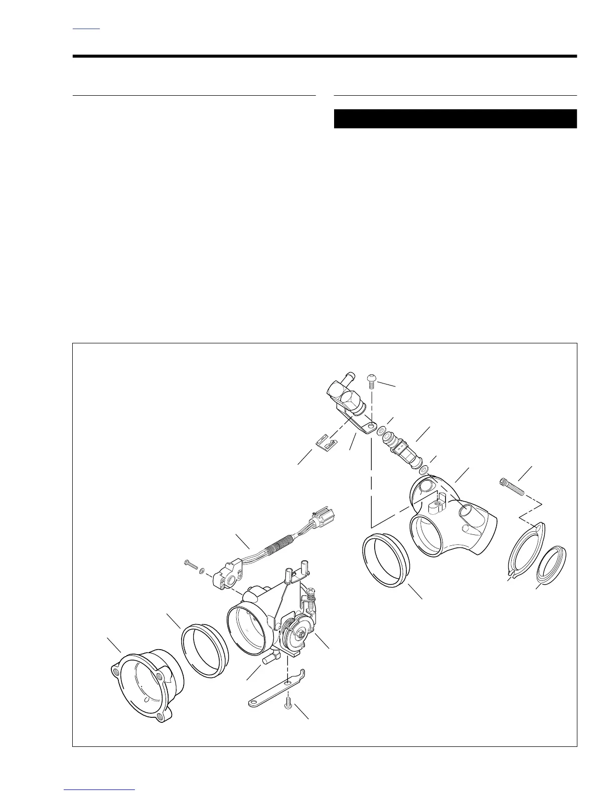
Figure 4-100. Throttle Body and Intake Manifold
1
2
6
5
4
2
14
15
7
13
12
11
9
8
1. Air Intake
2. Seal Ring (2)
3. EVAP Fitting
4. Rail and Screws (2) (metric)
5. Throttle Body
6. Throttle Position Sensor
7. Injector Clip (2)
8. Fuel Rail Assembly
9. Screw (metric)
10. Injector Seals (4)
11. Injector (2)
12. Intake Manifold
13. Screw (4)
14. Intake Flange (2, Front and Rear)
15. Intake Seal (2)
b0784x4x
3
10
10