2002 Buell X1: Electrical 7-43
HOME
TACHOMETER 7.18
GENERAL
Replace the tachometer if the unit is not working properly.
The instrument is not repairable. However, before replacing a
component, check that the problem is not caused by a loose
wire connection.
REMOVAL
1. Gain access to the back side of the dash panel. Detach
windscreen from mounting brackets by removing four
screws and washers.
2. See
Figure 7-60. Detach instrument support dash panel
(2) by removing two screws (1) holding panel to instru-
ment support clamp. Pull dash panel upward, but do not
damage wiring.
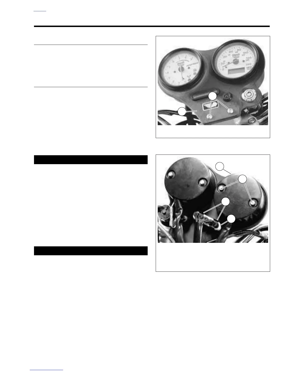
3. See
Figure 7-61. Remove two nuts (metric) (3) and lock-
washers (4) from tachometer cover (5).
4. Slide tachometer cover (5) away from tachometer.
CAUTION
Do not remove all the tachometer wires at the same time.
Only remove one wire at a time and reinstall screw imme-
diately. Failure to follow this caution will cause extreme
difficulty during reassembly.
5. See
Figure 7-62. Remove wires from tachometer.
a. Remove three lamps (1, 2, and 3) and attached
wires.
b. Loosen screws and remove wires (4, 5 and 6) one at
a time. After removing each wire, reinstall screw
immediately.
6. Pull tachometer from front of dash panel.
7. Remove rubber mounting gasket if necessary.
1WARNING1WARNING
The gasoline in the fuel supply line downstream of the
fuel pump is under high pressure (49 psi [338 kPa]). To
avoid an uncontrolled discharge or spray of gasoline,
always purge the system of high pressure gas before
attaching fuel pressure gauge. Gasoline is extremely
flammable and highly explosive. Inadequate safety pre-
cautions could result in death or serious injury.
8. If necessary, replace tachometer wiring.
a. Purge fuel line and remove fuel tank. See
4.37
FUEL TANK
.
b. Cut cable straps on wiring harness. See
Figure 7-
63. Detach wires at plug connector.
NOTE
Ta chometer and speedometer wiring share a common con-
nector [39] on the wiring harness.
Figure 7-60. Front Dash Panel
Figure 7-61. Back Dash Panel