7-44 2002 Buell X1: Electrical
HOME
INSTALLATION
1. If replacing tachometer wiring:
a. See
Figure 7-63. Attach wires at plug connector.
b. Feed wiring through wiring harness to dash panel
and secure with ties on electrical cabling.
c. Install fuel tank. See
4.37 FUEL TANK.
2. Install rubber mounting gasket if removed.
a. Apply 2 drops of adhesive (Permabond 105) at each
end of notches in gasket.
b. Apply 1 drop of adhesive (Permabond 105) at top of
gasket and bottom of gasket.
c. Position mounting gasket in dash panel.
3. Install tachometer in dash panel.
a. Feed wires through opening in tachometer cover.
b. Slide tachometer into rubber mounting gasket.
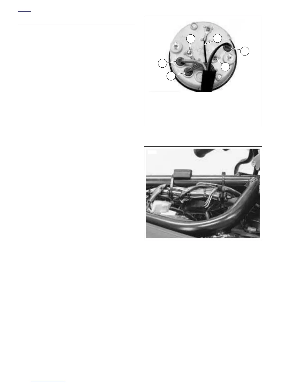
c. See
Figure 7-62. Insert lamps (1, 2 and 3) into their
appropriate bores.
d. Attach wires (4, 5 and 6) to tachometer as shown.
4. See
Figure 7-62. Install tachometer cover (5).
a. Place tachometer cover over tachometer. Align
posts on back of tachometer with holes in tachome-
ter cover. Drain hole must be at the bottom of cover.
b. Apply LOCTITE THREADLOCKER 243 (blue) to
both nuts (metric) (3).
c. Fasten cover (5) to tachometer using two nuts (met-
ric) (3) and lockwashers (4).
5. See
Figure 7-60. Position dash panel on instrument sup-
port clamp.
a. Attach dash panel using two screws (1) to hold
panel to clamp.
b. Tighten screws to 4-5 ft-lbs (5-7 Nm).
c. Attach windscreen to mounting brackets using four
screws and washers.
Figure 7-62. Tachometer Wiring
Figure 7-63. Tachometer Wiring Connector
Locations (Approximate)
1. Check Engine Lamp (BK/Y and O)
2. Low Fuel Lamp (Y and O)
3. Illumination Lamp (O and BK)
4. Signal (PK)
5. Ground (BK)
6. Power (O)
3
1
6941
6
4
5
2
6805
 Loading...


