3-22 2002 Buell X1: Engine
HOME
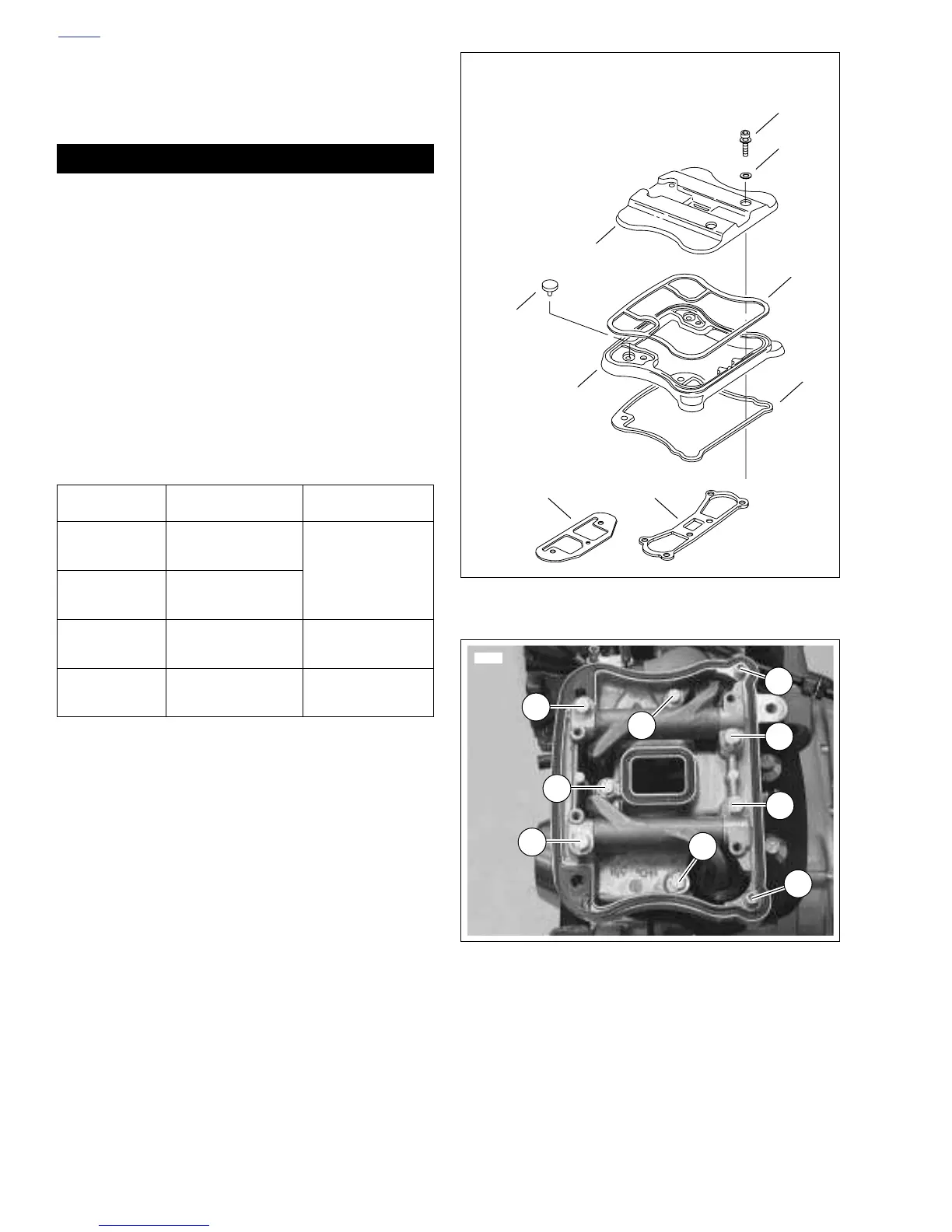
14. See Figure 3-29. Install new gaskets (8, 9) with the bead
facing up. Place lower rocker box assembly (with rocker
arms and shafts) into position. Place push rods in rocker
arm sockets.
CAUTION
Do not turn engine over until both push rods can be
turned with fingers. Otherwise, damage to push rods or
rocker arms may result.
15. See
Figure 3-30. Install fasteners (12, 13, 14 and 15).
Slowly snug all fasteners in small increments (one turn at
a time). Use a cross pattern on the four large bolts (12,
13) that fasten the lower rocker box to head. This will
bleed the lifters. Fastener sizes are listed in
Ta b l e 3-6.
a. Tighten bolts (12, 13) to 18-22 ft-lbs (24-30 Nm).
b. Tighten bolts (15) to 10-14 ft-lbs (14-19 Nm).
c. Tighten screws (14) to 130-150 in-lbs (14-19 Nm).
NOTES
Tu bular frame prohibits direct access to bolt (12) on right rear
cylinder. Use TORQUE ADAPTOR (SNAP-ON Part No.
FRDH 181) and TORQUE COMPUTER (SNAP-ON Part No.
SS-306G) to correctly assemble.
16. See Figure 3-29. Install middle and upper rocker covers.
a. Place a new gasket (7) on lower rocker box assem-
bly.
b. Install middle rocker cover (5) with umbrella valve
next to intake manifold.
c. Place a new gasket (6) on middle rocker cover.
d. Install upper rocker cover (4) using screws with
washers (1) and new fiber seals (2). Tighten screws
to 10-14 ft-lbs (14-19 Nm).
17. Install the other cylinder using the same procedure.
Table 3-6. Lower Rocker Box Hardware
ITEM SIZE TORQUE
Bolt with
washer (12)
5/16-18 X 2-3/4
15-19 ft-lbs
(20-26 Nm)
Bolt with
washer (13)
5/16-18 X 2-1/2
Screw with
washer (14)
1/4-20 X 1-1/2
130-150 in-lbs
(15-17 Nm)
Bolt with
washer (15)
1/4-20 X 1-1/4
10-14 ft-lbs
(14-19 Nm)
Figure 3-29. Rocker Arm Cover Gaskets
Figure 3-30. Lower Rocker Box Fasteners
(Same Numbers as
Figure 3-6.)
1. Screws with Washers (4)
2. Fiber Seal (4)
3. Umbrella Valve (2)
4. Upper Rocker Cover
5. Middle Rocker Cover
6. Gasket
7. Gasket
8. Gasket
9. Gasket
b0506x3x
1
2
4
6
7
98
3
5
13
14
12
12
15
15
15
14
13
6616













 To Next Page