4-18 2002 Buell X1: Fuel System
HOME
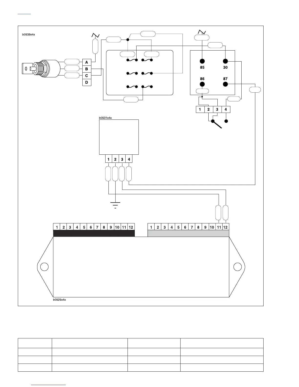
Figure 4-17. Diagnostic Check
R
R
R/GY
R/BK
R/GY
R/BK
R/BK
R/BK R/BK
GY/O
Ignition 20A
Memory 15A
Spare 15A
Lights 15A
Instruments 15A
Accessory 15A
Ignition
Switch
[33]
Engine Stop
Switch [22]
TN/W
Ignition Relay
W/BK
GY/O
To Main Circuit
Breaker
To Starter
Interlock Circuit
Electronic Control Module
(ECM)
Connector [10] Connector [11]
Lt GN/R
V/R
Data
Link
[91A]
Lt GN/R
V/R
BK
GY
GY
Table 4-6. Wire Harness Connectors in Figure 4-17.
NO. DESCRIPTION TYPE LOCATION
[10] ECM (black) 12-place Deutsch under seat
[11] ECM (gray) 12-place Deutsch under seat
[91A] Data link 4-place Deutsch behind right side of steering head