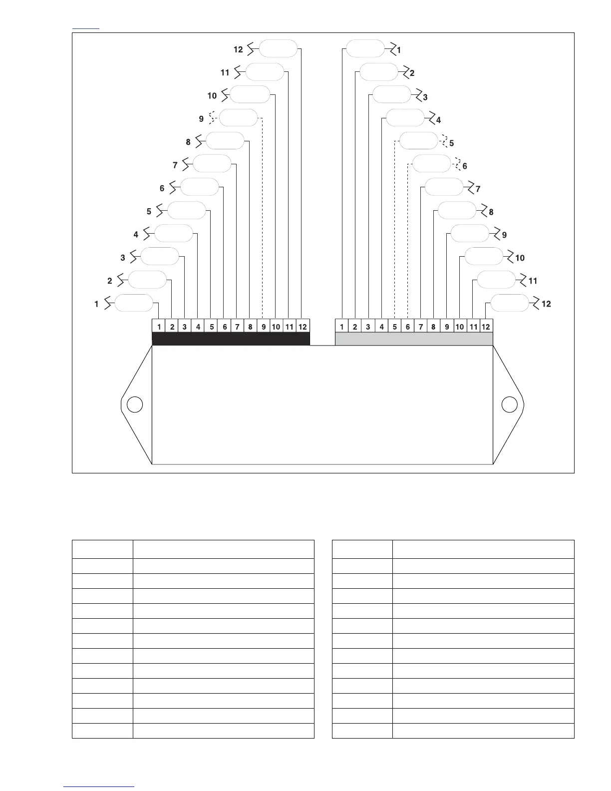
Table 4-27. Pin Table for
ECM Connector [10] (Black)
PIN FUNCTION
1 Switched ignition
2System ground A (module)
3 Fuel pump output
4 Check engine lamp
5Injector front output
6Front coil primary
7 Rear coil primary
8Injector rear output
9 No function
10 Bank angle sensor input
11 System ground B (coil)
12 Tachometer out
Table 4-28. Pin Table for
ECM Connector [11] (Gray)
PIN FUNCTION
15 volt sensor power
2Throttle position sensor
3 Camshaft position sensor
4Oxygen sensor
5 No function
6 No function
7 Sensor ground 1
8 Sensor ground 2
9 Engine temperature input
10 Intake air temperature input
11 Serial data receive
12 Serial data transmit