2002 Buell X1: Electric Starter 5-17
HOME
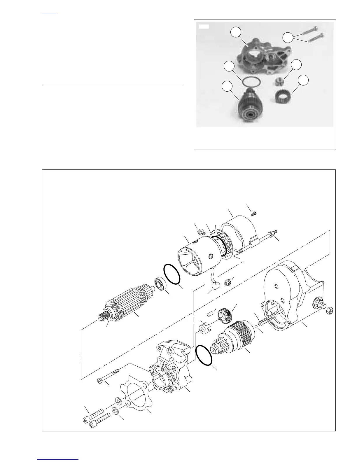
15. See Figure 5-25. Remove two drive housing mounting
screws (6). Remove drive housing (5) from solenoid
housing.
16. Remove drive (1), idler gear (2), idler gear bearing (3),
and O-ring (4) from drive housing (O-ring is located in
drive housing groove).
ASSEMBLY
1. See
Figure 5-25. Clean, inspect and lubricate drive
assembly components. Lubricate parts with high temper-
ature grease, such as LUBRIPLATE 110.
2. See
Figure 5-26. When installing drive assembly compo-
nents, open end of idler bearing cage (15) faces toward
solenoid.
3. When installing drive housing (10) to solenoid housing
(11), use new O-ring (16). Be sure to install return spring
(17) and ball (18). Figure 5-25. Starter Drive Assembly
 Loading...


