2002 Buell X1: Drive/Transmission 6-9
HOME
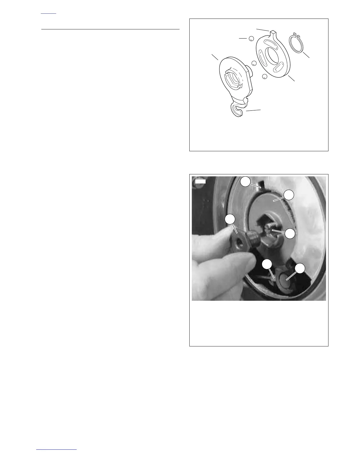
ASSEMBLY
1. See
Figure 6-11. Assemble inner and outer ramp.
a. Apply multi-purpose grease to balls (2) and ramps
(1, 3).
b. Insert balls in sockets of outer ramp (1).
c. Install inner ramp (3) on hub of outer ramp (1) with
tang 180° from hook of outer ramp.
d. Install new retaining ring (4) in groove of outer ramp
hub.
2. See
Figure 6-12. Install ramp assembly.
a. Fit coupling (5) over cable end (4) with rounded side
inboard, the ramp connector button outboard.
b. With retaining ring side of ramp assembly facing
inward, place hook of ramp around coupling button.
c. Rotate assembly counterclockwise until tang on
inner ramp fits in slot of primary cover (6).
3. Secure assembly in place.
a. Thread wellnut (2) on adjusting screw (3) until slot of
screw is accessible with a screwdriver.
b. Fit nut hex into recess of outer ramp (1).
c. Turn adjusting screw counterclockwise until resis-
tance is felt.
4. Adjust clutch release mechanism. See 1.10 CLUTCH.
5. Connect negative battery cable to battery terminal.
Figure 6-11. Inner and Outer Ramp
Figure 6-12. Nut and Outer Ramp