6-36 2002 Buell X1: Drive/Transmission
HOME
13. See Figure 6-62. Install two socket head screws (5)
through aligned holes of lockplate and into tapped holes
of sprocket. Tighten screws to 90-110 in-lbs (10-12 Nm).
NOTE
The original equipment socket head screws (5) have thread-
locking compound applied to them. Since this compound
remains effective for about three removal/installation cycles,
the original screws may be reused up to three times. After the
third removal/installation cycle, replace both screws with new
screws identical to the original.
14. Install the remaining removed components in the reverse
order of the removal procedures. See the procedures
listed in the respective component sections.
15. Adjust drive belt tension. See
1.11 DRIVE BELT
DEFLECTION
.
16. Fill transmission to proper level with fresh lubricant. See
1.10 CLUTCH.
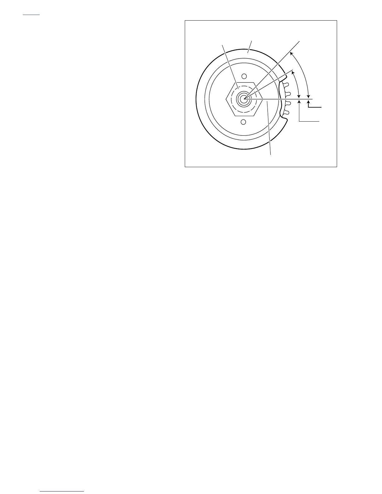
Figure 6-64. Aligning Transmission Sprocket
45°
30°
Transmission
Sprocket
Transmission
Sprocket Nut
Line scribed on nut and sprocket
i00077-