7-38 2002 Buell X1: Electrical
HOME
INSTALLATION
Right Side
1. Attach throttle cables to hand control. See
2.24 THROT-
TLE CONTROL.
2. Position housings on right handlebar by engaging locat-
ing pin on front housing with hole in handlebar. Attach
housings with two screws (1, 6), installing longer screw
on bottom. Tighten screws to 12-17 in-lbs (1-2 Nm).
3. See
Figure 7-52. Route switch housing wiring harness
between front forks and along right side frame tube.
Attach connector [22] and, if necessary, connector [21] to
wiring harness. Fasten wiring harness to frame with new
cable straps.
4. Install fuel tank. See
4.37 FUEL TANK.
1WARNING1WARNING
After installing seat, pull upward on front of seat to be
sure it is locked in position. If seat is loose, it could shift
during vehicle operation and startle the rider, causing
loss of control which could result in death or serious
injury.
5. Install seat. See
2.40 SEAT.
6. Adjust throttle cables. See
1.20 THROTTLE CABLES.
1WARNING1WARNING
Check all handlebar switch operations before riding
motorcycle. Visibility is a major concern for motorcy-
clists. Handlebar switches not operating properly could
result in death or serious injury.
7. Check handlebar switch for proper operation. If operation
fails, reread procedure and verify that all steps were per-
formed.
a. Turn ignition key switch to IGN.
b. Start motorcycle.
c. Turn ignition key switch to OFF.
Left Side
1. Attach switch housing to handlebar with three screws.
Tighten screws to 25-33 in-lbs (3-4 Nm).
2. See
Figure 7-53. Route switch housing wiring harness
between front forks and along right side frame tube.
Attach connector [24] and, if necessary, connector [95}
to wiring harness. Fasten wiring harness to frame with
new cable straps.
3. Install fuel tank. See
4.37 FUEL TANK
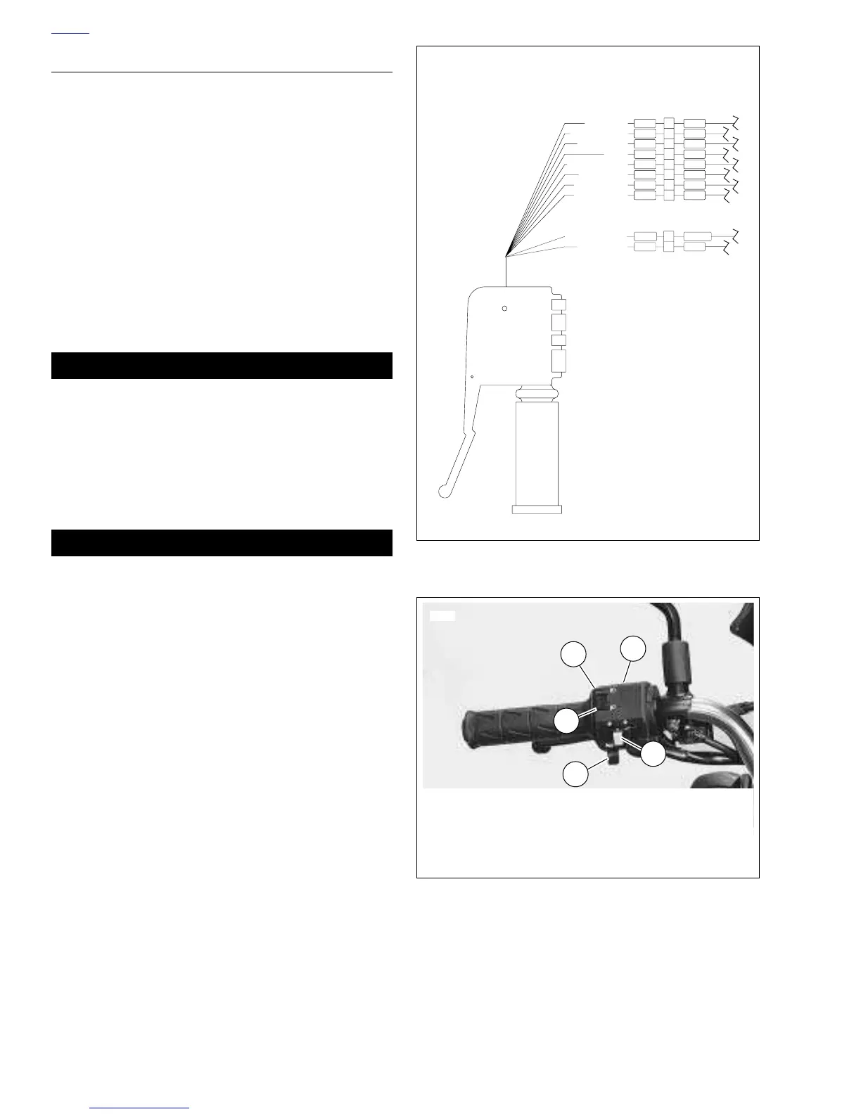
Figure 7-50. Left Handlebar Switch Connection
Figure 7-51. Left Handlebar Switches
V
GY
LtBE
O
2
BE
GN
BK
BN
W
RIGHT TURN
9
8
7
6
5
3
1
W
Y/BK
V/BN
BN
O/W
Y
BE
HORN POWER
LEFT TURN
FROM FLASHER
HIGH BEAM
HORN
LIGHT POWER
LOW BEAM
R/BE
TN/GN
BK
2
1
BK
FROM IGN RLY
TO GROUND
b0631x7x
Clutch Switch [95]
Left Handlebar Switch [24]
1. Passing Lamp
2. HIGH Beam
3. LOW Beam
4. Turn Signals
5. Horn
1
2
4
5
3
6926
 Loading...


