1-38 2002 Buell X1: Maintenance
HOME
6. See Figure 1-49. Set static timing. This will align open-
ings (1, 2) on trigger cup with cam position sensor.
a. Set engine stop switch to RUN.
b. Tu rn ignition switch to IGN.
c. See
Figure 1-46. Loosen two screws (5) on cam
position sensor (7). Rotate sensor clockwise until
the voltmeter registers the change from 0.0-1.0 VDC
to 5.0 VDC (+/- 0.5 volts).
d. Tighten both sensor screws (5) to 10-20 in-lbs (14-
27 Nm).
7. Install inner cover (4), inner cover screws (3), outer cover
(2) and new outer cover rivets (1).
8. Install spark plugs, shift transmission into neutral and
remove jack.
9. Remove BREAKOUT BOX harness and connect elec-
tronic control module connector [11].
11WARNING1WARNING
After installing seat, pull upward on front of seat to be
sure it is locked in position. If seat is loose, it could shift
during vehicle operation and startle the rider, causing
loss of control which could result in death or serious
injury.
10. Install seat. See
2.40 SEAT.
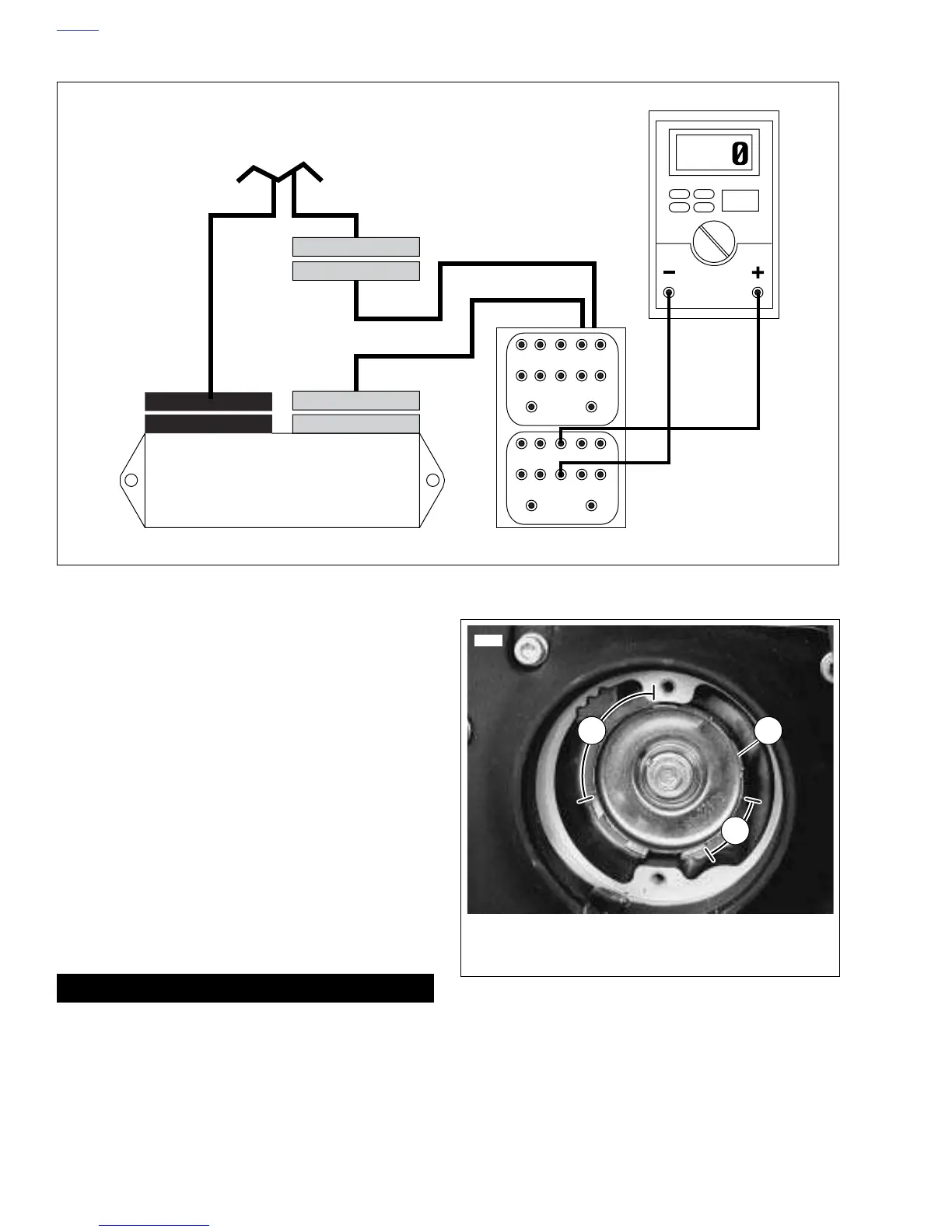
Figure 1-48. Static Timing Connections
1
6
2
7
3
8
4
9
5
VDC
10
11 12
1
6
2
7
3
8
4
9
5
10
11 12
Black
Gray
Continues to Main
Wiring Harness
Electronic Control
Module
(+) Lead to Gray 3
(-) Lead to Gray 8
b0636x7x
Connector [10] Connector [11]
Figure 1-49. Trigger Cup Openings
(Cam Position Sensor Removed For Illustration)
6889
2
1
1. Large Opening
2. Small Opening
3. Front Cylinder Top Dead Center Window
3