19
Mechanical installation
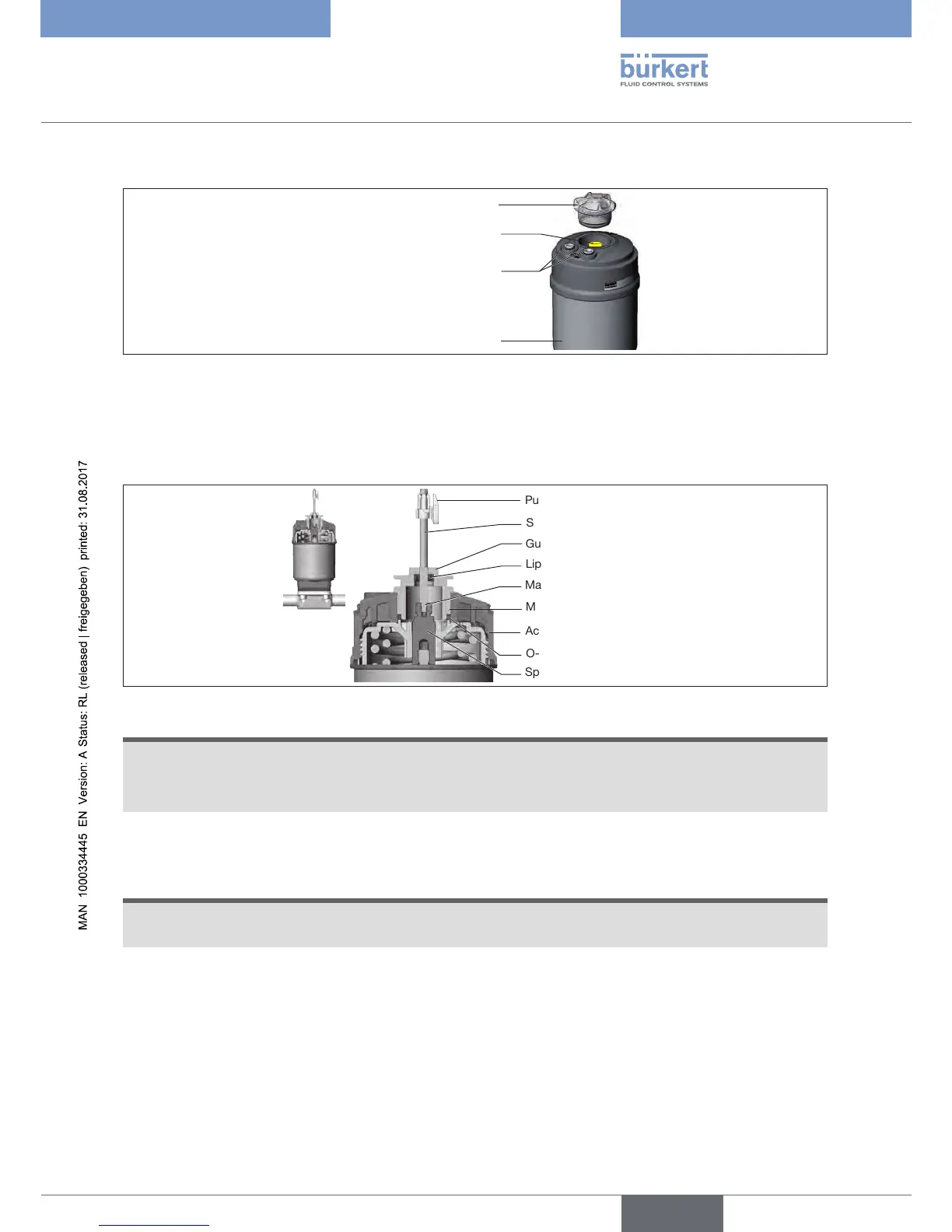
1. Installing the switch spindle
Transparent cap
Actuator
Pilot air ports
(plug-in connectors with collets or
threaded bushings)
Position indicator
Figure 7: Installing the switch spindle (1), integrated pilot air duct
→ Unscrew the transparent cap from the actuator.
→ Unscrew position indicator from spindle extension.
→ For variant with hose connector: remove the collets (white sleeves) from the pilot air ports.
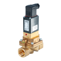
Spindle extension
Guide element
Actuator cover
Lip seal
Puck
Switch spindle
Max. 5 Nm
Max. 1 Nm
O-ring
Figure 8: Installing the switch spindle (2), integrated pilot air duct
NOTE
Lipsealcanbedamagedifincorrectlyinstalled.
The lip seal is pre-mounted in the guide element and must be "locked into position" in the undercut.
▶ When installing the switch spindle, do not damage the lip seal.
→ Slide switch spindle through the guide element.
NOTE
Contaminationofthelipsealduetoscrewlockingpaint.
▶ Do not apply any screw locking paint to the switch spindle.
→ To secure the switch spindle, apply some screw locking paint (e.g. Loctite 290) in the threading of the
spindle extension in the actuator.
→ Check that the O-ring is in the correct position.
→ Screwguideelementinactuatorcover(tighteningtorque:max.5Nm).
→ Screw switch spindle onto the spindle extension. A slot is provided on the top side (tightening torque:
max.1Nm).
→ Push puck onto the switch spindle and lock into position.