32
Electrical installation
9.3 Connecting the device electrically, büS
1 2
34
5
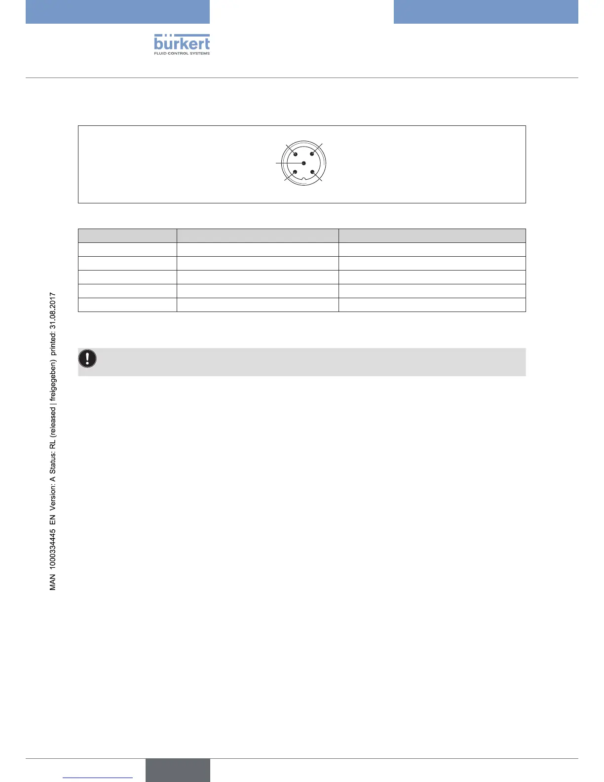
Figure 24: Pin assignment
Pin Wire color Assignment
1 CAN plate/shielding CAN plate/shielding
2 red +24 V DC ± 10%, max. residual ripple 10%
3 black GND / CAN_GND
4 white CAN_H
5 blue CAN_L
Table 5: Pin assignment
ForelectricalinstallationwithbüSnetwork,note:
Use a 5-pin round plug and shielded 5-core cable.