38
Installation
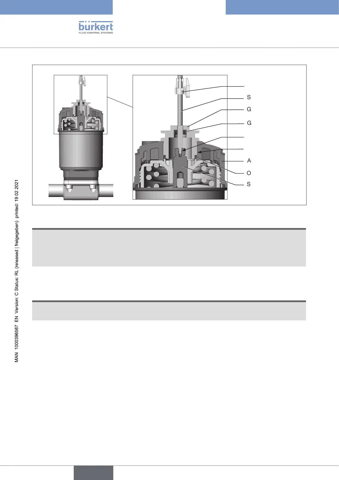
Spindle extension
Guide element
Actuator cover
Groove ring
Puck
Switch spindle
max. 5 Nm
max. 1 Nm
O-ring
Figure 19: Installation of the switch spindle (2), series 2103, 2300 and 2301
ATTENTION!
Improperinstallationmaydamagethegrooveringintheguideelement.
Thegrooveringisalreadybepre-assembledintheguideelementandmustbe“lockedintoposition”
intheundercut.
▶ When installing the switch spindle, do not damage the groove ring.
→ Push the switch spindle through the guide element.
ATTENTION!
Screwlockingpaintmaycontaminatethegroovering.
▶ Do not apply any screw locking paint to the switch spindle.
→ To secure the switch spindle, apply some screw locking paint (Loctite 290) in the tapped bore of the spindle
extension in the actuator.
→ Check that the O-ring is correctly positioned.
→ Screw the guide element to the actuator cover (maximum torque: 5 Nm).
→ Screw switch spindle onto the spindle extension. To do this, there is a slot on the upper side
(maximum torque: 1 Nm).
→ Push puck onto the switch spindle and lock into position.
english
Type 8694 REV.2