42
Installation
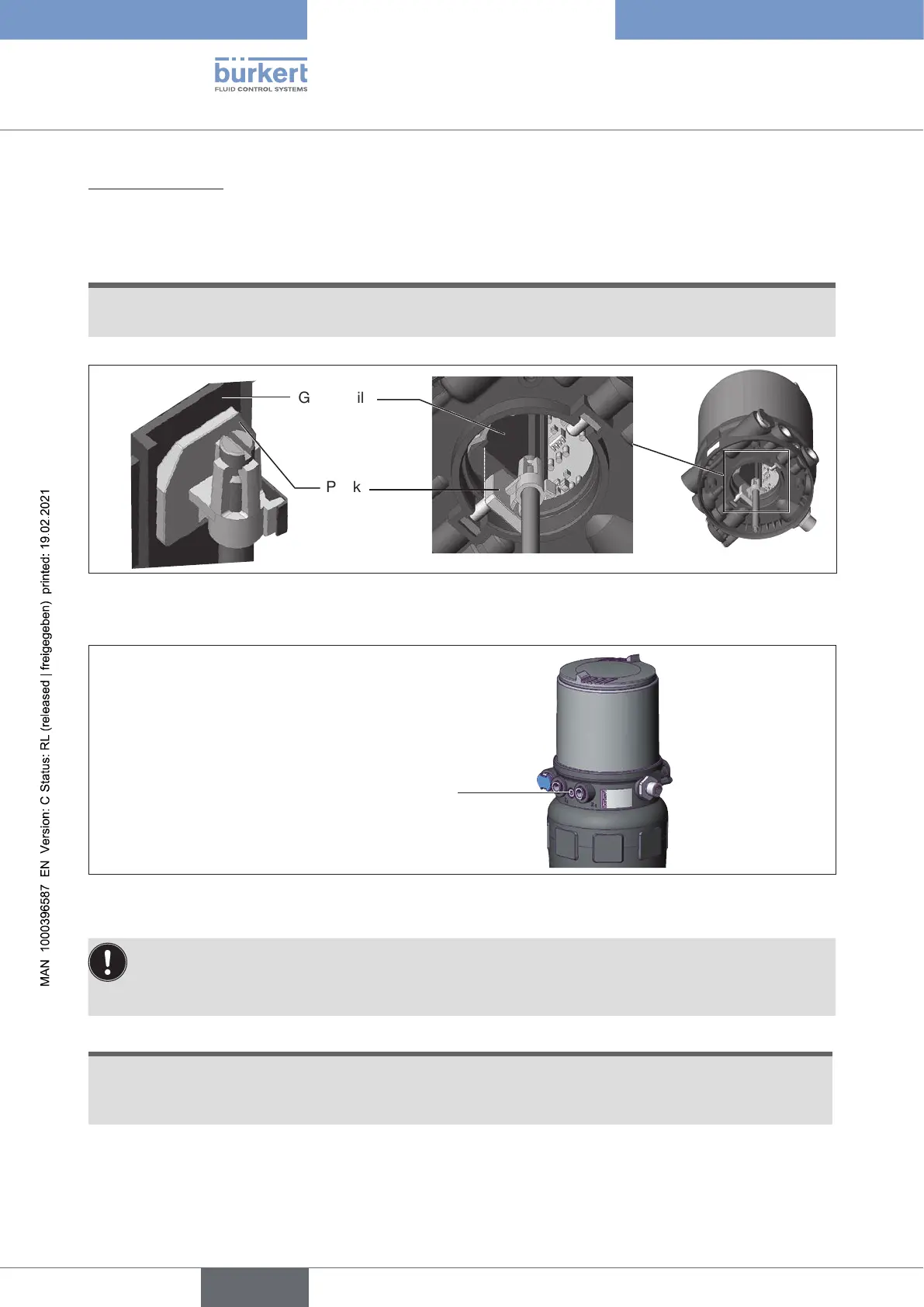
2.Installpositioner
→ Push the positioner onto the actuator. The puck must be aligned in such a way that it is inserted into the
guide rail of the positioner.
ATTENTION!
Damagedprintedcircuitboardormalfunction.
▶ Ensurethatthepuckissituatedatontheguiderail.
Guide rail
Puck
Figure 25: Aligning the puck
→ Press the positioner all the way down as far as the actuator and turn it into the required position.
Fastening screws
max. 1.5 Nm
Figure 26: Installing the positioner
Ensure that the pneumatic connections of the positioner and those of the valve actuator are situated
preferably vertically one above the other.
Iftheyarepositioneddierently,longerhosesmayberequiredotherthanthosesuppliedinthe
accessory kit.
ATTENTION!
ToohightorquewhenscrewinginthefasteningscrewdoesnotensuredegreeofprotectionIP65/
IP67.
▶ The fastening screws may be tightened to a maximum torque of 1.5 Nm only.
→ Attach the positioner to the actuator using the two side fastening screws. In doing so, tighten the fas-
tening screws hand-tight only (maximum torque: 1.5 Nm).
english
Type 8694 REV.2