43
Installation
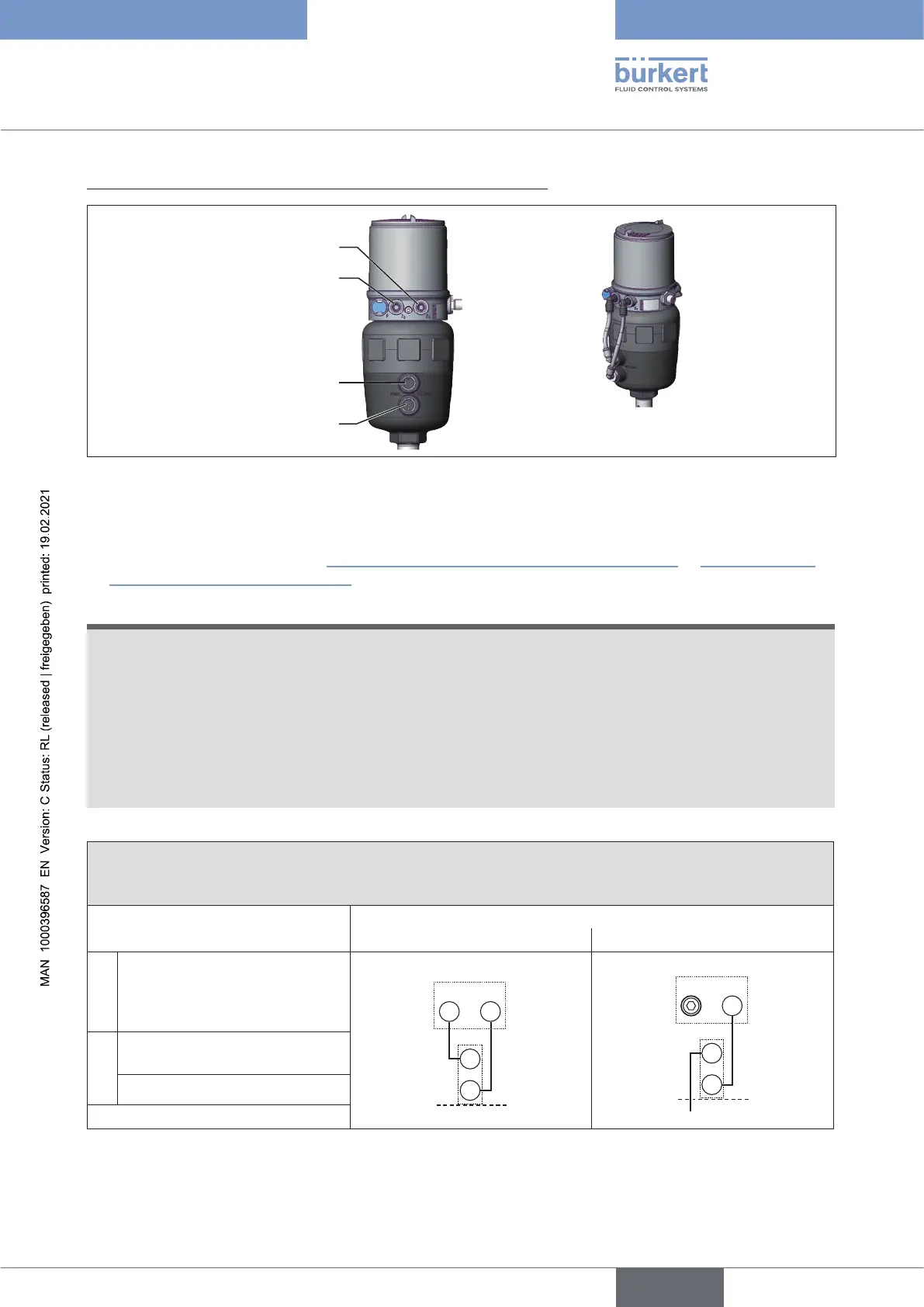
3.Installpneumaticconnectionbetweenpositionerandactuator
Pilot air outlet 2
1
Pilot air outlet 2
2
Upper pilot air
port
Lower pilot air
port
Example ∅ 80, CFA
Figure 27: Installing the positioner
→ Screw the plug-in hose connectors onto the positioner and the actuator.
→ Using the hoses supplied in the accessory kit, make the pneumatic connection between the positioner
and actuator with the following “Table17:Pneumaticconnectiontoactuator,CFA” or “Table18:Pneu-
maticconnectiontoactuator,CFB”.
ATTENTION!
Damageormalfunctionduetoingressofdirtandmoisture.
To observe degree of protection IP65 / IP67:
▶ In the case of actuator size ∅ 80, ∅ 100
connect the pilot air outlet which is not required to the free pilot air port of the actuator or seal with a
plug.
▶ In the case of actuator size ∅ 125
seal the pilot air outlet 22 which is not required with a plug and feed the free pilot air port of the actuator
via a hose into a dry environment.
ControlfunctionA(CFA)
Process valve closed in rest position (by spring force)
Actuator size ∅ 80, ∅ 100
∅ 125
Positioner
Pilot air outlet
2
2
2
1
2
2
2
1
Actuator
Upper pilot air port
Lower pilot air port
Dryarea
Table 17: Pneumatic connection to actuator, CFA
english
Type 8694 REV.2