54
Electrical installation 24 V DC
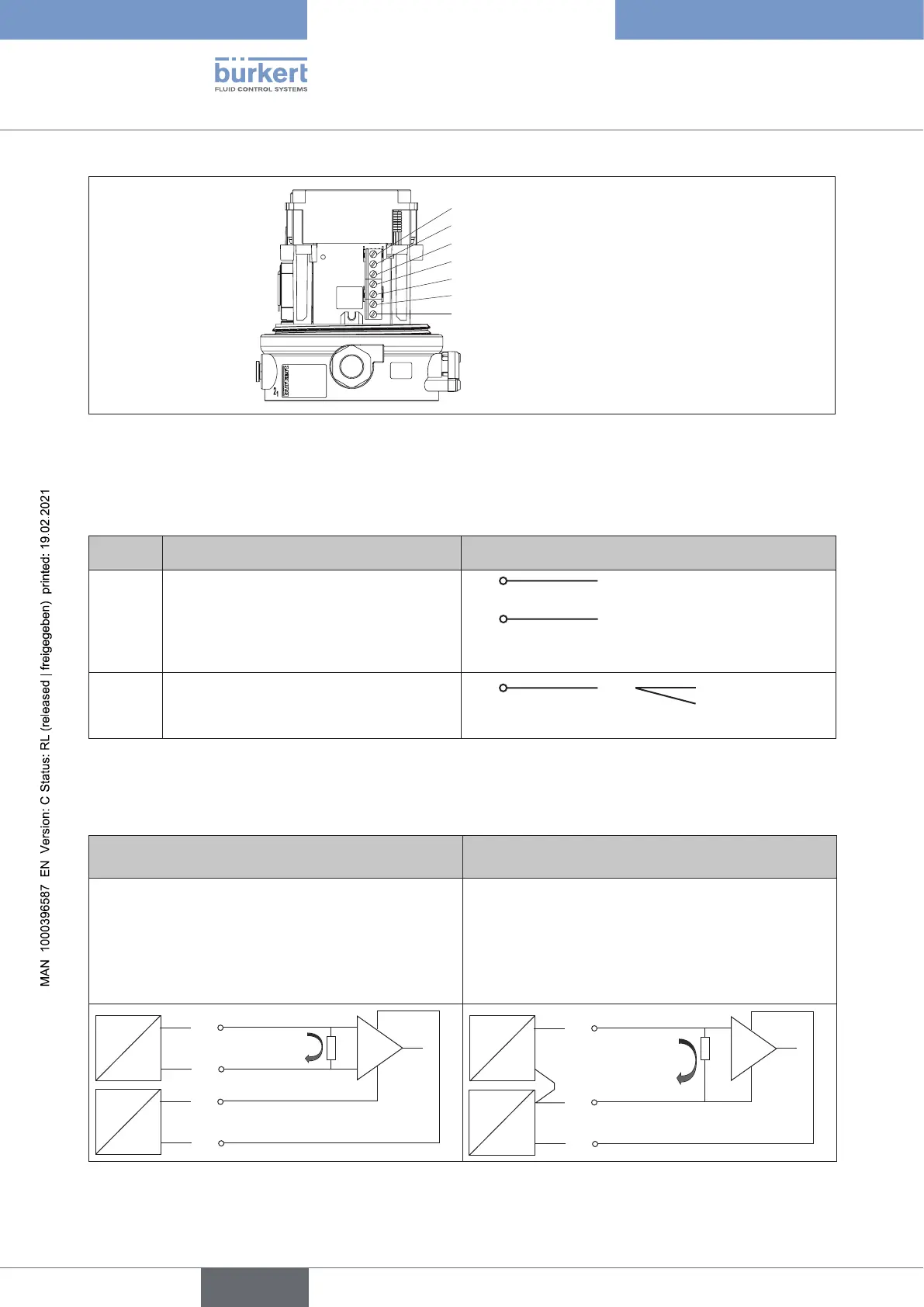
1
2*
3*
4
5
6
7
* Only for variant with
analog output
Figure 38: Connection of screw-type terminals
→ Connect the positioner according to the following tables:
Input signals from the control centre (e.g. PLC)
Terminal Conguration Externalcircuit
4
5
Set-point value +
Set-point value GND
4
5 GND
seetable”Connectiontype
3-wireor4-wire”
+ (0/4 – 20 mA)
1
Digital input +
1 + 0 – 5 V (logical 0)
10 – 30 V (logical 1)
with reference to terminal 7 (GND)
Table 23: Assignment of screw-type terminals, input signals of the control center, cable gland
Connection type 3-wire or 4-wire (setting via communication software):
Connectiontype4-wire(factorysetting) Connectiontype3-wire
Theset-pointvalueinputisdesignedasadier-
ential input, i.e. the GND lines of the set-point value
input and the supply voltage are not identical.
Note: If the GND signals of the set-point value input
and the supply voltage are connected, the 3-wire
connection type must be set in the software.
The set-point value input is related to the GND line
of the supply voltage, i.e. setpoint input and supply
voltage have a common GND line.
4
5
0/4-20 mA
7
6
GND
+24 V DC
+
+
U
I
4
0/4-20 mA
7
6
GND
+24 V DC
+
+
U
I
Table 24: Connection type
english
Type 8694 REV.2