55
Electrical installation 24 V DC
Output signals to the control center (e.g. PLC; for analog output option only)
Terminal Conguration Externalcircuit
2
3
Analogue position feedback +
Analogue position feedback GND
2
3 GND
+ (0/4 – 20 mA)
Table 25: Assignment of screw-type terminals, output signals to the control center, cable gland
Operatingvoltage
Terminal Conguration Externalcircuit
6
7
Operating voltage +
Operating voltage GND
6
7
24 V DC ± 25 %
max. residual ripple 10 %
Table 26: Assignment of screw-type terminals, operating voltage, cable gland
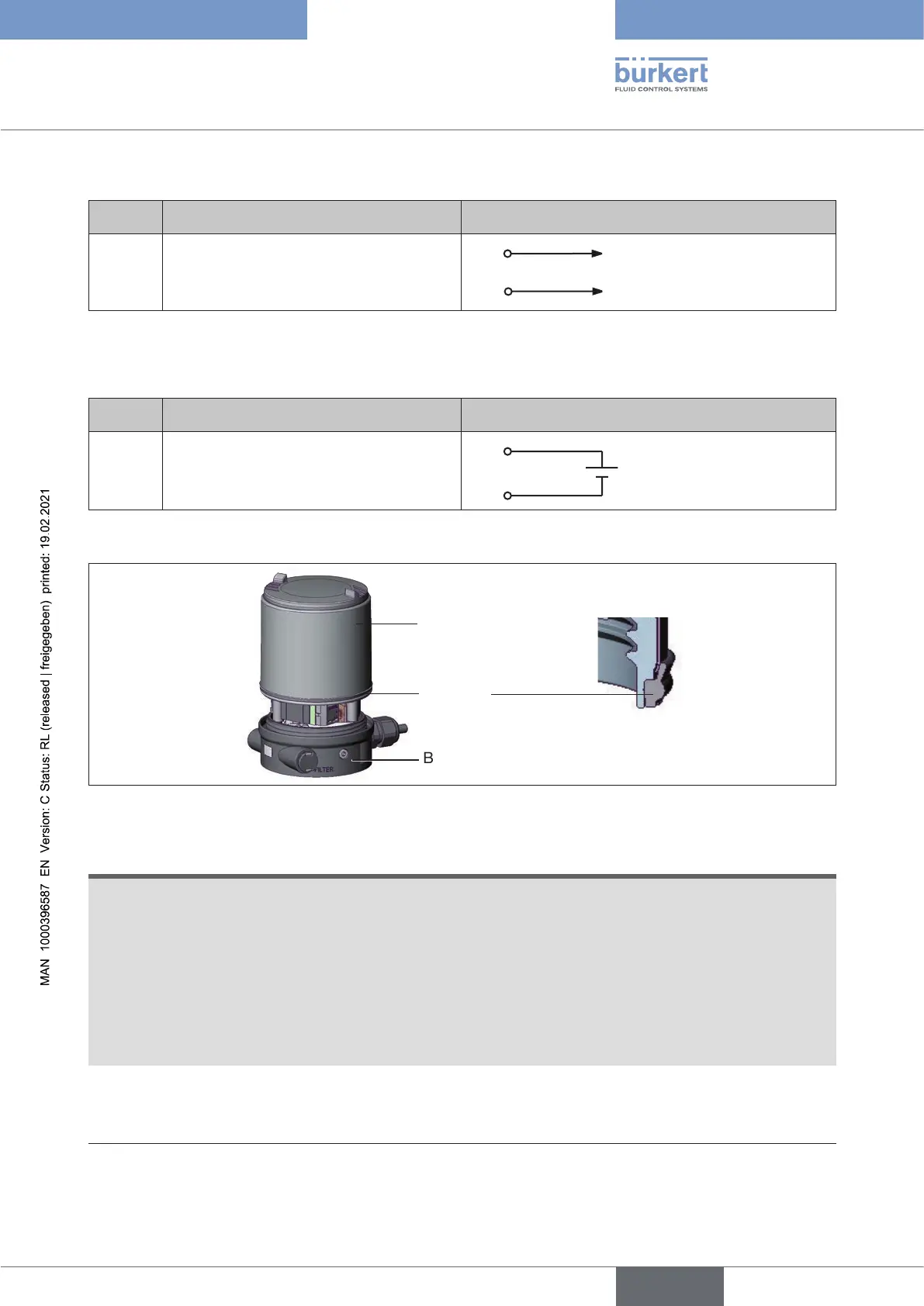
Seal
body casing
Body casing
Basic housing
Figure 39: Position of the seal in the body casing
→ Check that the seal is correctly positioned in the body casing.
ATTENTION!
Breakageofthepneumaticconnectionpiecesduetorotationalimpact.
▶ When unscrewing and screwing in the body casing, do not hold the actuator of the process valve but
the basic housing.
Damageormalfunctionduetopenetrationofdirtandhumidity.
To ensure degree of protection IP65 / IP67:
▶ Tighten the union nut on the cable gland according to the cable size or dummy plugs used (approx. 1.5 Nm).
▶ Screw the body casing in all the way.
→ Tighten union nut on the cable gland (torque approx. 1.5 Nm).
→ Close the device (assembly tool: 674077
25)
).
25) The assembly tool (674077) is available from your Bürkert sales oce.
english
Type 8694 REV.2