Translation of the Original Operating Manual
4.6 Mixing and dispenser unit
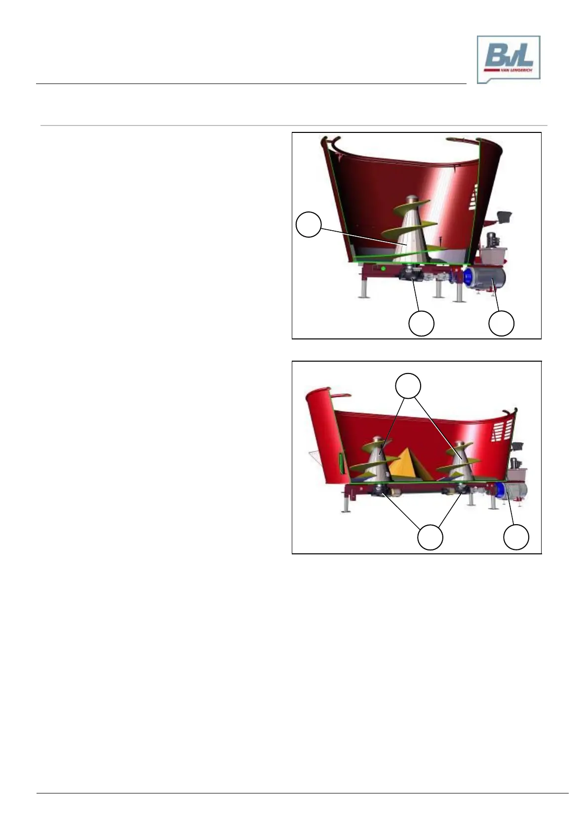
The mixing and dispenser unit on the V-MIX Fix Plus 1S
comprises:
a mixing auger (1),
a gear unit (2),
a gear motor (3).
The gear motor (3) drives the gear unit (2). The rotation-
al movement of the mixing auger (1) is, in turn, initiated
by the gear unit (2).
The mixing auger (1) reduces, mixes, and transports the
silage to the discharge opening.
Fig. 4-8 Container with dispenser unit V-MIX Fix Plus 1S
(Sectional view)
The mixing and dispenser unit on the V-MIX Fix Plus 2S
comprises:
two mixing augers (1),
two gear units (2),
a gear motor with drive shaft (3).
The gear motor (3) drives the gear units (2). The rota-
tional movement of the mixing augers (1) is, in turn, initi-
ated by the gear units (2).
The mixing augers (1) reduce, mix, and transport the
silage to the discharge opening.
Fig. 4-9 Container with dispenser unit V-MIX Fix Plus 2S
(Sectional view)