The reduced and mixed silage is discharged via the dis-
charge opening.
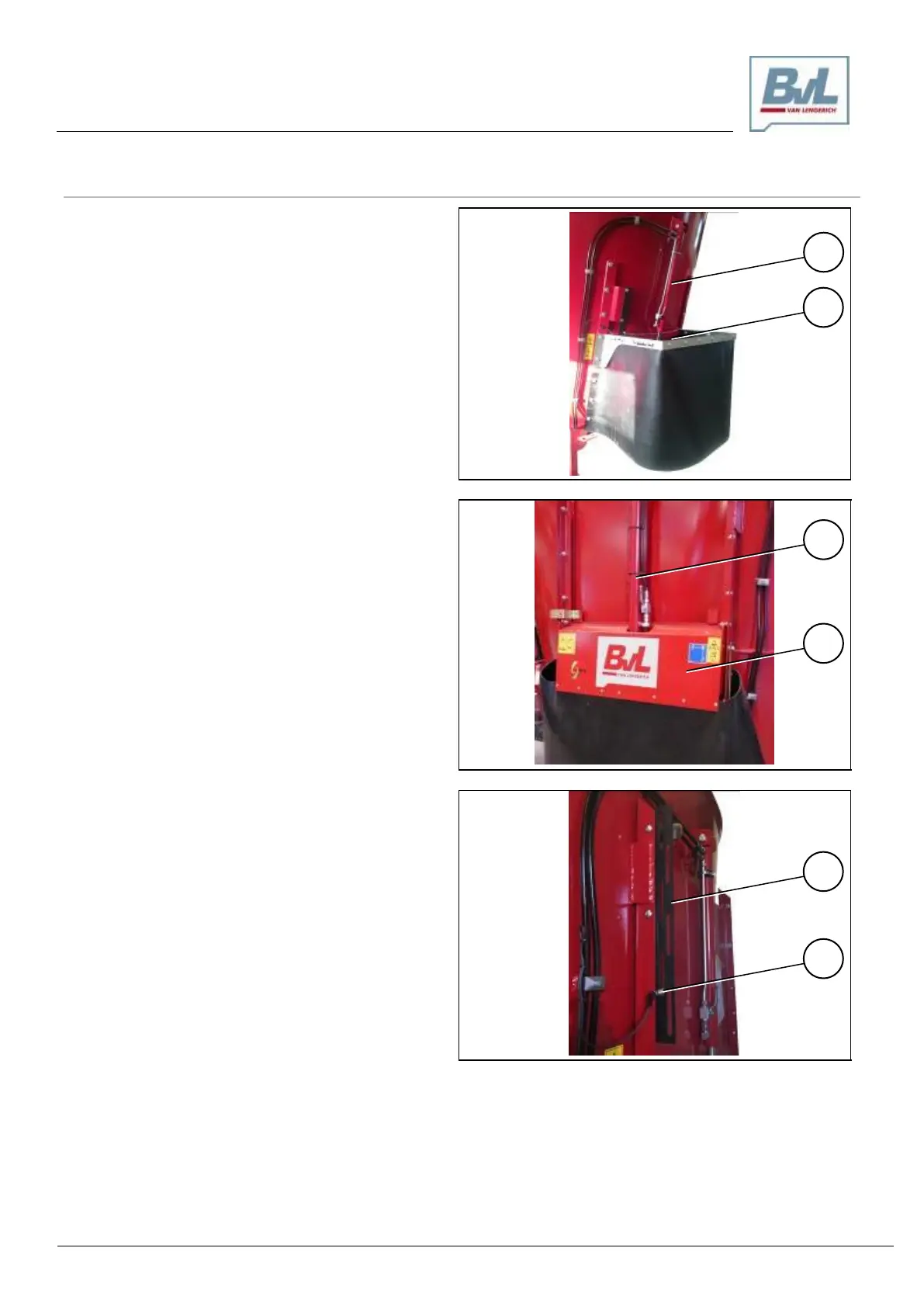
The dosing gate (2) is opened and closed by the hydrau-
lic cylinder (1).
The hydraulic cylinder (1) is actuated using the controls
(pos. 3, 4, 5) at the control switch cabinet (see page 52).
If the dosing gate (2) is equipped with a sensor (4), the
opening movement of the dosing gate (2) will stop at the
level of the sensor (4).
The switching strip (3) has six slotted holes which can be
used to affix and continuously adjust the sensor (4).
Opening the dosing gate automatically in emptying
mode
If the “Mix/Deliver” selector switch (see page 52) is set to
“Deliver“, the dosing gate will open and stop its opening
movement upon reaching the level of the sensor (4).
The switching strip (3) has six slotted holes which can be
used to affix and continuously adjust the sensor (4).