186 ARTEMIS Digital Broadcast Production Console Glossary of Terminology
ADC (Analogue to Digital
Conversion)
The process by which continuous
analogue signals are sampled
and converted into discrete digital
representations. The frequency of
samples in the resultant digital signal is
determined by the Sample Rate of the
system (e.g. 48kHz). The dynamic range
of the sampled signal is dependent on the
wordlength (e.g. 24bit).
AFL
After-Fade Listen. Allows the user to
hear only the selected channels after they
have been affected by fader position, pan
position and channel processing. Multiple
AFL signals can be sent to the AFL bus.
AFL does not affect the main outputs, so
can be seen as being similar to ‘safe solo’.
APFL
A bus that combines both AFL and PFL
signals. This removes the need to have
separate loudspeakers and meters for
monitoring AFL and PFL signals.
Assign Mode
An operating mode of the surface in which
it acts as an assignable console. A fader
is assigned and all controls on an assign
panel become relevant to the assigned
path.
Assign Panel
When a fader panel is set to operate
in Assign Mode, it can be referred to
as an Assign Panel. The controls and
information on this panel will reflect
the data associated with the currently
assigned path.
Assigned Path
When a path is assigned, certain
functionality becomes available to it.
For example the spill controls can affect
components of a multichannel path, or any
Assign Panels can update to display and
control data relevant to the assigned path.
Aux / Auxiliary
An Aux is a bus to which signals can
be sent and grouped. The send for the
originating channel may be pre or post
fade. Auxs can be patched to output
ports and can be controlled by certain
logic functions such as pre-send cut when
originating channel is cut, pre-send cut
when originating channel fader is closed
and Bird Beater.
Auto Fade
Faders can be set to fade in and out in
response to GPI signals. This might be
set up so that a vision mixer can control
relevant audio sources by simply fading up
or down the video signal.
Bird Beater
With the function turned on for a given
Aux, the pre-fade send from an originating
channel can be cut when the originating
fader is opened and not cut.
Bluefin 2
The next generation of Calrec’s High
Density Signal Processing (HDSP)
system. Capable of over 1000 input
channel paths from just a single card.
Broadcast Facilities Panel
A panel located in the surface upstand.
This provides access to useful broadcast
functions such as TX/REH modes,
system reset indicators and buttons, a
talkback microphone input and a USB
port for the configuration PC.
Bus Path
A path in which multiple signals can be
combined. A bus is the general term
and can refer to a number of path types
including Group, Aux, Track, Main, Mix
Minus, AFL, PFL.
Button Cell
A collection of four buttons around a
display.
Calrec Assist
This is a web browser application which
when connected to a console, allows an
alternative control interface which works
in parallel.
Channel Faders
Channel Faders are located on the Fader
Panels. Channels, groups, mains can all
be attached to them allowing assignment
and level control. They may also be used
to control VCA groups.
Configuration PC
The configuration PC is a Windows based
computer linked to a touchscreen external
to the surface, normally mounted on a
flexible arm. This PC provides access to
system settings.
Continuous Memory
A continually updated memory that stores
the state of the system. In the event of
a restart after power loss or reset, the
system can reload the continuous memory
and continue from almost the same state
prior to power loss.
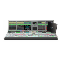
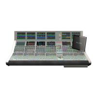
Control Bed
The main, shallow angled area of the
control surface as oppose to the upstand.
The Artemis control bed can be fitted
with fader and monitor panels. An Apollo
control bed has a second row, mainly
populated with assignable control panels.
Control Cell
The collection of controls consisting of a
display, two buttons & two rotary controls.
Control Processor Module
The control processor module acts as the
main controller of the Artemis system,
passing messages between all modules.
The surface communicates with the rack
via the control processor module.