44 ARTEMIS Digital Broadcast Production Console Getting Signals Into Artemis
ALLOCATING SIGNAL PATHS TO FADERS
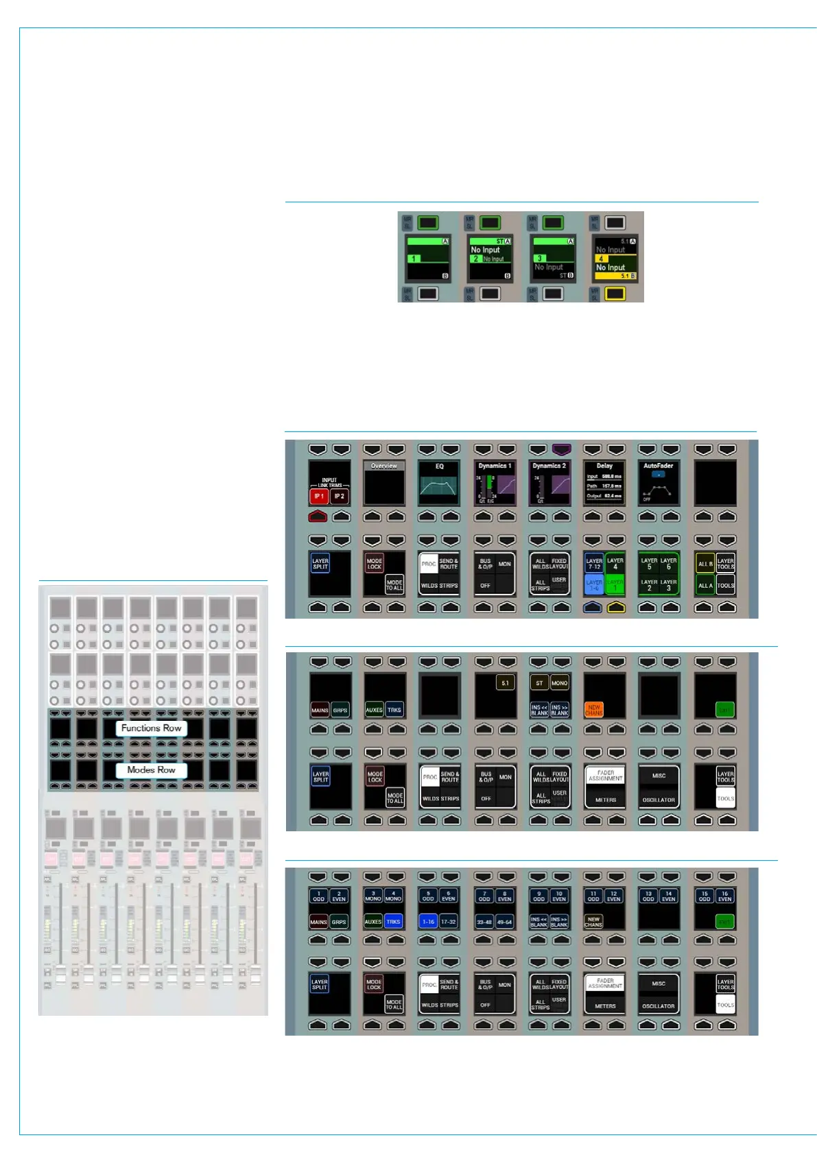
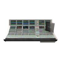
FIG 1 - CONTROL ROW LOCATIONS
FIG 4 - MODES AND FUNCTIONS ROWS - TOOLS>FADER ASSIGNMENT>NEW CHANS
FIG 5 - MODES AND FUNCTIONS ROWS - TOOLS>FADER ASSIGNMENT>TRACKS*
FIG 3 - MODES ROW - DEFAULT VIEW
Each fader’s label display is split
to show A layer information in the
upper half and B layer information
in the lower half. If either portion of
the label display is blank, other than
the fader number and the A / B layer
indication, it does not have any signal
path associated with it on that layer.
Input channels, audio group buses and
Main output buses are all DSP paths that
can be allocated to and controlled by
faders. The allocation of paths on faders
is saved as part of the user memory.
Assigning channels to faders
Selecting the Tools menu from the right
hand side of the Modes row replaces
the fader layer selection buttons with
Tools sub-menu selection buttons. The
selected sub-menu is displayed in the row
above. See Figs 1,3,4 & 5
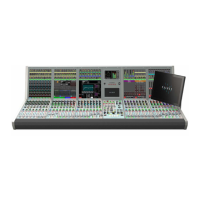
FIG 2 - LABEL DISPLAYS FOR FADERS 1-4
In Fig 2 above, fader 1 has no signal paths allocated. Fader 2 has a stereo input channel
path on the A layer, and the A layer is currently active. Fader 3 has a stereo input
channel path on the B layer, but its A layer is active. Fader 4 is active on the B layer
and has surround input channels on both A and B layers. Note, the input channels are
labelled ‘NO INPUT’ as no input source has yet been patched to the channel path.
*Note: Auxs and Tracks on Faders available in V7.0 onwards