CALREC Putting Sound in the Picture 47
Any locked paths placed between the
insertion point for the blank and a free
fader will also prevent paths from shuffling
and stop the blank being inserted.
Layer locking faders
Faders can be prevented from changing
layer by locking them to the layer they
are currently on, providing a means of
ensuring chosen paths are always close
to hand.
Layer locked faders display a padlock
icon in their label display and their assign
buttons flash when a layer change is
performed to highlight them as locked and
not changing. See Fig 9 below.
To lock paths, press and hold the LAYER
LOCK button in the LAYER TOOLS menu
whilst selecting the assign buttons of
the faders to be locked. Use the same
process to unlock a fader.
When a fader is unlocked, it does not
automatically change layer to that of the
rest of the console. It will remain on its
own layer until the next layer change is
performed.
Note that layer locking does not prevent
paths being overwritten by memory loads
Please refer to the Memory Isolation
section for this feature.
Copying path settings
Settings for a given path may be copied
over to another path. You can choose
whether to copy all settings, or just a
certain subset of the settings.
The elements which can be copied are:
• IP1 + DELAY ( Input 1 settings - 48V,
input trim, SRC and input delay)
• IP2 + DELAY (Input 2 settings - 48V,
input trim, SRC and input delay)
• EQ 1-4 (EQ bands 1-4)
• EQ 5-6 (EQ bands 5-6)
• DYN1
• DYN2
• PATH DELAY (Path delay settings)
• FDR + D-MIX (Fader level and down
mix levels if used)
• DIR O/P + DELAY (Direct output and
output delay settings)
• TO M/G (Routing to mains and groups)
• TO TRK (Routing to tracks)
• TO AUX (Routing to Auxiliaries)
• WILDS
• AUTOFADER
• ALL (All of the above elements)
Note, when copying settings which
include assignable (input and output)
delay, the delay settings will only be
copied if the destination already has
the delay assigned. The copy function
is just for the delay setting, not the
delay itself.
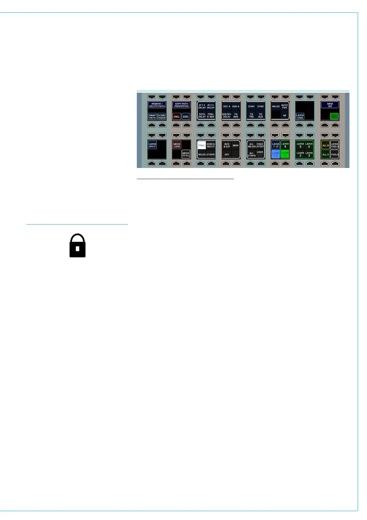
To access the copy function, push the
LAYER TOOLS button and the row above
will display the controls shown in Fig 10
above.
To copy path settings:
1. Use the middle four button cells to
select the path elements that you wish
to copy by toggling on/off the buttons
above each option.
FIG 9 - LAYER LOCKED FADER ICON
FIG 10 - COPY PATH PROPERTIES
2. Press the assign button of the path
from which you wish to copy settings.
3. Now press and hold the COPY CHAN
PROPERTIES button and whilst
holding, press the assign button(s) of
any paths you wish to copy the settings
to. Release all buttons and then press
the EXEC or CNCL buttons to confirm
or cancel the copy respectively.
Some important points to note:
• If you are copying the properties of a
stereo/surround spill leg the stereo/
surround master will be used as the
copy source.
• If any copied properties do not apply to
the copy destination, those properties
will not be copied, for example Balance
settings will not be copied from a
stereo to a mono path.
• If a path’s properties are copied to
a path of a different width, only the
master settings for the path will be
copied.
• Input 1/2 switching and TONE on/off
switching will not be copied.
Warnings and Conflicts
When copying path properties it may be
the case that now path settings create
conflicts, for example, when altering the
input settings of a shared input port.
If a conflict does arise a pop-up will
appear on the TFT to inform you along
with the usual Input/Output sharing pop-
up on the main application screen.
See “Input Port Protection” on page 58
for more information.