82 ARTEMIS Digital Broadcast Production Console Processing Audio
STEREO/SURROUND SPILL
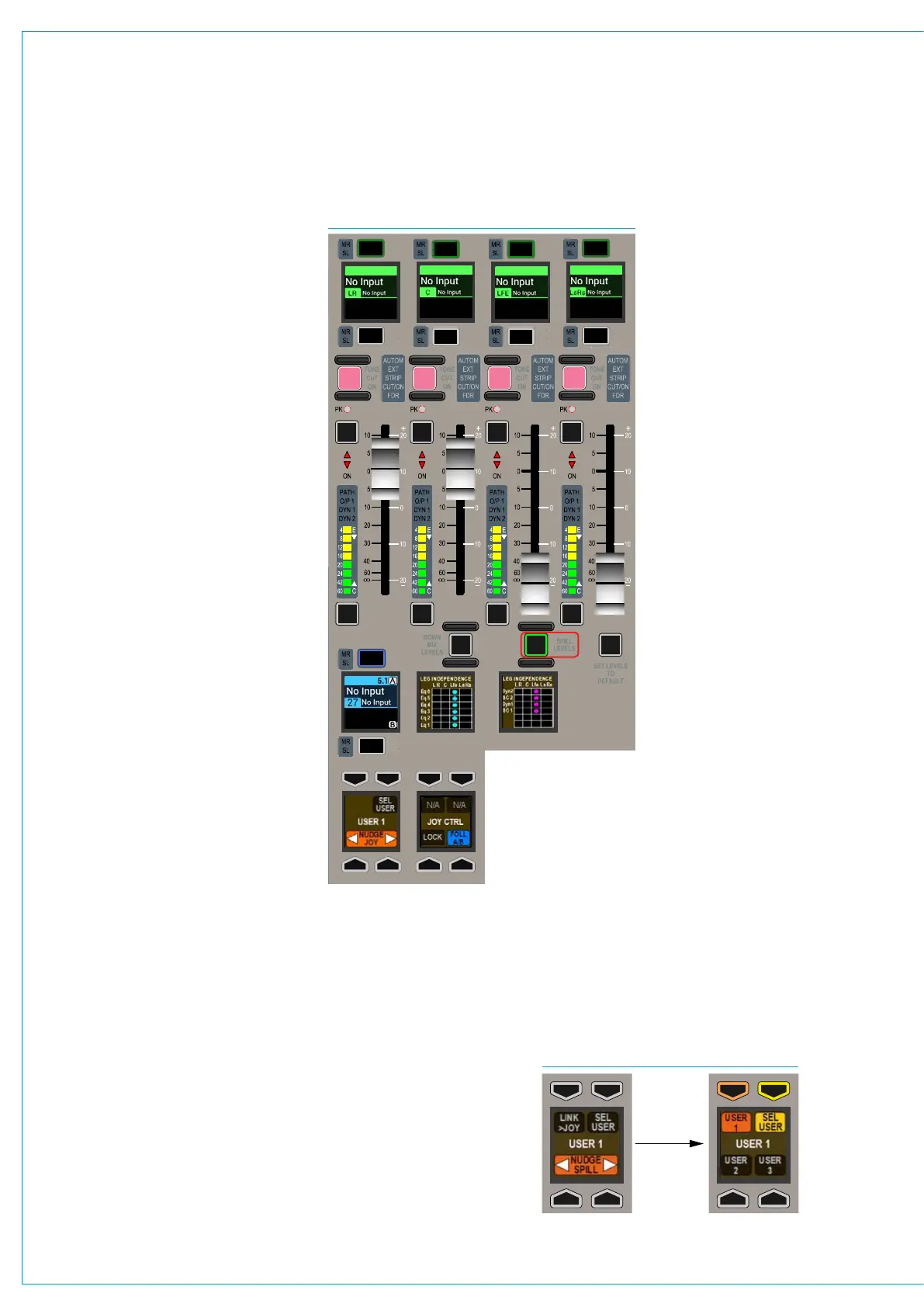
FIG 1 - SPILL CONTROLSSpill controls provide the ability to
control the elements that make up a
stereo or surround path independently.
If a full-featured dedicated monitor panel is
fitted, the user has access to spill controls.
Please note that there is an alternate
dedicated monitor panel type which does
not have spill fader or joystick controls.
Accessing the spill faders
Fig 1 shows the relevant area of the full-
featured dedicated monitor panel in spill
mode. To enter spill mode, press the SPILL
LEVELS button beneath the third fader.
The display beneath the first fader shows
which path is the focus of the spill controls.
Note that spill controls are only active for
surround or stereo paths.
If FOLL A/B is selected from the SPILL
CTRL button cell, at the bottom of the spill
control area, the focus of the spill controls
follows the currently assigned path on the
surface (or within the selected user split if
the console has been set up for multiple
operators). Selecting LOCK from the same
button cell prevents the focus of the spill
controls from changing. The NUDGE left
& right buttons in the adjacent control cell
allow the focus to be changed without
selecting path assign buttons, moving
the focus left or right across the surface.
The SEL USER button in this cell allows for
different user splits to be selected when
set up for multiple operators.
Note that the joystick controls, have similar
button cells, but can be focused on a
different path to the spill controls. The two
different areas of controls are demarcated
by the background colour of the panel.
Four sets of fader controls and labels are
located in the upper section of the panel.
In spill mode, with a surround path selected
as the focus, the first set of fader controls
are for front Left & Right, the second set
for the Centre channel, the third set for the
LFE channel, and the fourth set for the rear
Ls Rs channels.
In spill mode with a stereo
path selected, the first two
faders control the left and
right channels. PFL & AFL
buttons allow each element
to be listened to pre and post
fader.
The faders themselves allow
for the level that each element
outputs to be set individually.
The level of the output is a
combination of the spill fader
and the stereo/surround
path’s master fader.
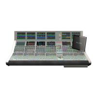
Changing the user section
When multiple operators are using the surface, it is
possible for any of them to access the spill controls
for paths assigned in their own user sections.
Press the SEL USER button in the lower button cell
of the spill control area as shown in Fig 2 below.
This will update the rest of the control cell display
to display the three user sections. Press the button
corresponding to the required user section that the
spill controls should respond to and then press the
SEL USER button again. The chosen user section
will be shown in the middle of the display and the spill
faders will respond to that users path assignments.
CUT CUT
CUT
CUT
AFL
PFL
AFL
PFL
AFL
PFL
AFL
PFL
Therefore if all spill faders are
closed for example, there will
be no output from the path,
irrespective of the stereo/
surround master fader position.
Cut buttons above each fader
allow for each element to be cut
independently.
Assigning paths on the
spill panel
Pressing the assign button
above a spill fader label display
makes that specific element of
the stereo/surround path the
currently assigned path on the
console, and therefore the focus
of assignable mode panels
to allow parameter changes
such as gain, EQ, routing
etc to be set independently
for each element. When a
stereo/surround element is
the currently assigned path,
the stereo/surround master’s
assign button remains blue but
strobe to indicate any controls
applied are not affecting the
path as a whole.
FIG 2 - SEL USER