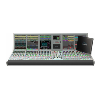
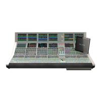
22 ARTEMIS Digital Broadcast Production Console Control Overview
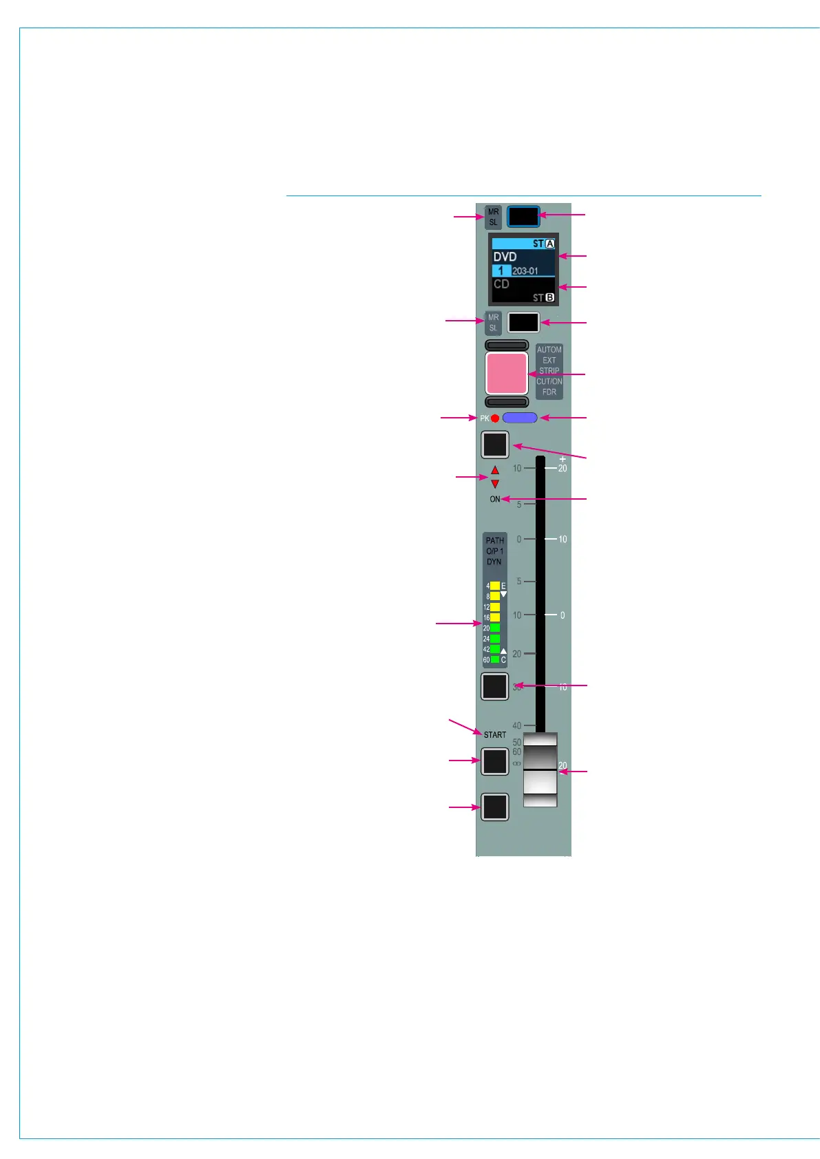
The lower section of the standard control
bed panels contain the path faders and
associated controls.
The controls are laid out in 8 identical,
vertically aligned strips. Each fader
has an A and B sub-layer which can be
switched between by pressing the assign
buttons above and below the fader’s label
display. The two sub-layers are not related
by default and can control two distinct,
unrelated audio paths. The upper half
of the label display, when active is green
and relates to the A layer. The lower half,
when active is yellow and relates to the B
layer. An open fader will remain open and
passing audio after the layer has been
changed.
Pressing the assign button above (A
layer) or below (B layer) the label display
makes it the currently assigned path
and highlights it blue. Only one path
(unless user splits are in place) can
be the currently assigned path at any
given time. The currently assigned path
is the focus of the assignable panel
m o d e s , P R O C E S S I N G & S E N D - R O U T E .
The information shown on these panels
and any parameter changes made from
them relate to the currently assigned
(highlighted blue) path. See Fig 2.
As well as selecting A/B sub-layers on
a fader by fader basis, the ‘All A’ & ‘All B’
buttons located in the left hand button
cell of the modes row will switch all faders
(unless user or layer splits are in place)
between sub-layer A & B.
In addition to A & B sub-layers, there are a
total of 12 fader layers, each with an A &
B sub-layer. All layers and A/B sub-layers
are active irrespective of which layer is
currently visible. Changing fader Layers
1-12 affects all the faders in the control
surface unless layer or user splits have
been put in place, or the fader has been
locked to the surface.
FIG 2 - FADER / PATH CONTROLS
A layer assign button
A layer input / path label
B layer input / path label
A layer VCA group master /
slave indication
B layer VCA group master /
slave indication
Path cut button
(or optional ‘on’ button)
Audio peak / overload
indicator
After Fader Listen button
(overrides monitor LS)
Null LED’s - indicate when
fader is in incorrect position,
e.g if movement is blocked
Fader on (open) indicator
Illuminated indicator (colour
dependent on path type)
Input audio bargraph
Isolate button (prevents the
path being overwritten by
user memory load)
Talkback to path
direct / mix-minus output
Pre-Fader Listen button
100mm motorised fader
shown at off position. Pull
back for overpress activation
of PFL
Fader controlled GPIO start
indicator
CUT
AFL
PFL
DIR
TB
ISO
B layer assign button