13
INSTALLATION
INSTALL THE LIMIT SWITCHES
In case there are no mechanical stops, securing and adjusting the operations for the
endstop unit are mandatory. NOTE: The images show a left-hand installation.
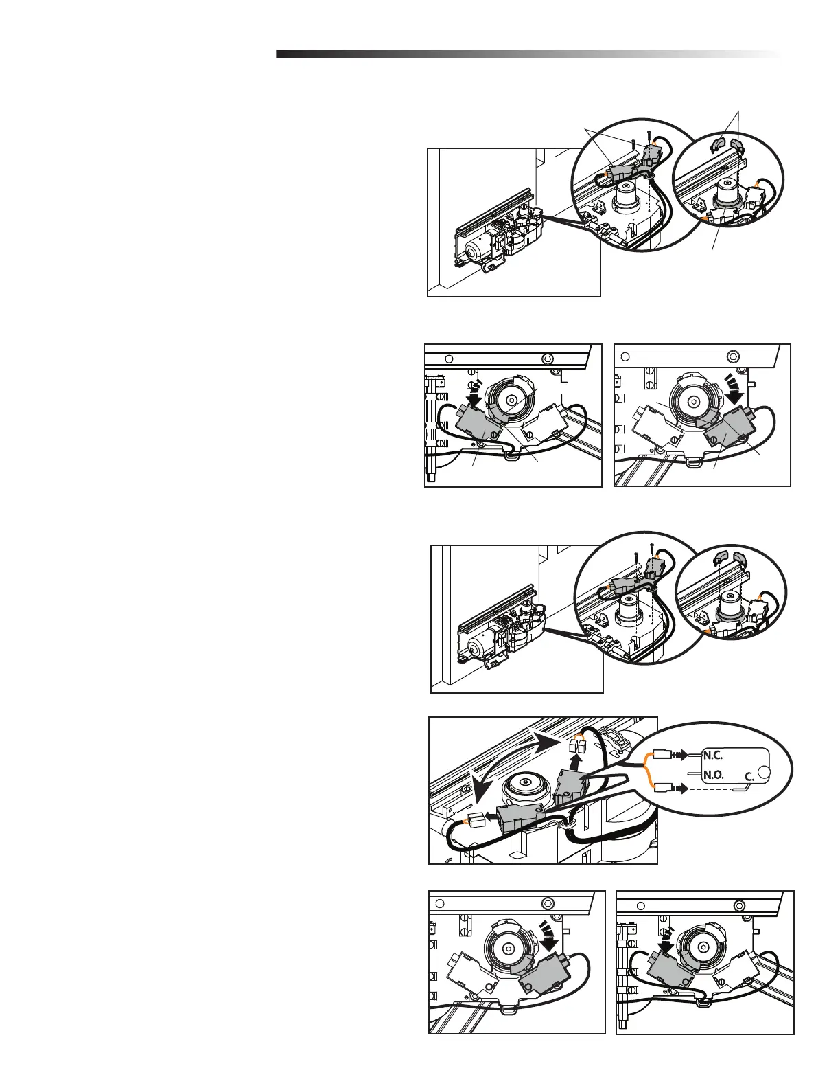
LEFT-HAND INSTALLATION
1
Secure the limit switches to the operator (Figure 1).
2
Attach the cams onto the cam guide on the operator (Figure 1).
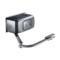
3
Close the gate. Rotate the close cam counter-clockwise until it comes into
contact with the close limit switch (red wires). Secure the close cam in this
position by turning the screw (Figure 2).
4
Open the gate. Rotate the open cam clockwise until it comes into contact with
the open limit switch (white wires). Secure the open cam in this position by
turning the screws.
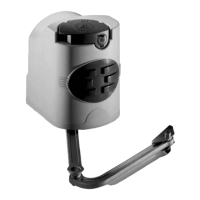
RIGHT-HAND INSTALLATION
1
Secure the limit switches to the operator (Figure 4).
2
Attach the cams onto the cam guide on the operator (Figure 4).
3
Reverse the wires on the limit switches as shown (Figure 5).
4
Close the gate. Rotate the close cam clockwise until it comes into contact with
the close limit switch. Secure the close cam in this position by turning the
screw (Figure 6).
5
Open the gate. Rotate the open cam counter-clockwise until it comes into
contact with the open limit switch. Secure the open cam in this position by
turning the screws (Figure 7).
Figure 1
INSTALL THE LIMIT SWITCHES
Figure 2 Figure 3
Limit Switches
Cams
Cam Guide
Close Cam
Close Limit Switch
Open Cam
Open Limit Switch
Screw
Screw
Figure 4
Figure 5
Figure 6 Figure 7