17
M
N
N
M
M1 N1 E1 + E -
M2 N2 E2 + E -
CFCC FAM N
+E -
ADT06
CFCC FAM N
+E -
ADT06
-
E
+
+
E
-
Control panel
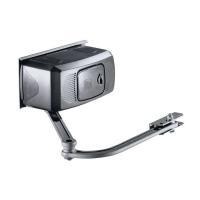
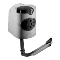
Left gearmotor
Right gearmotor
Junction box
Junction pit
Junction box
WIRE THE OPERATOR(S) TO THE
CONTROL PANEL
When making electrical connections, use the pit for the junction boxes.
1
Turn off the AC power from the main power source circuit breaker.
2
Insert the power cable through the watertight connector on the bottom of the
operator. Connect the wires from the power cable to the board on the
operator as shown.
3
Insert the other end of the power cable through a watertight connector
mounted in the back of the control panel. Connect the wires from the power
cable to the terminals on the control panel as shown.
Do not apply AC power until instructed.
NOTE: The electronic card is equipped with an amperometric sensor which
constantly monitors the motor’s drive. If the gate encounters an obstacle, the sensor
immediately detects the overload on the operator and the gate reverses.
WIRE THE OPERATOR(S) TO THE CONTROL PANEL
WIRING
Terminals on Control Panel (ZLJ24)
24 Vdc operator with delayed opening
24 Vdc operator with delayed closing