Chapter 3
3-17
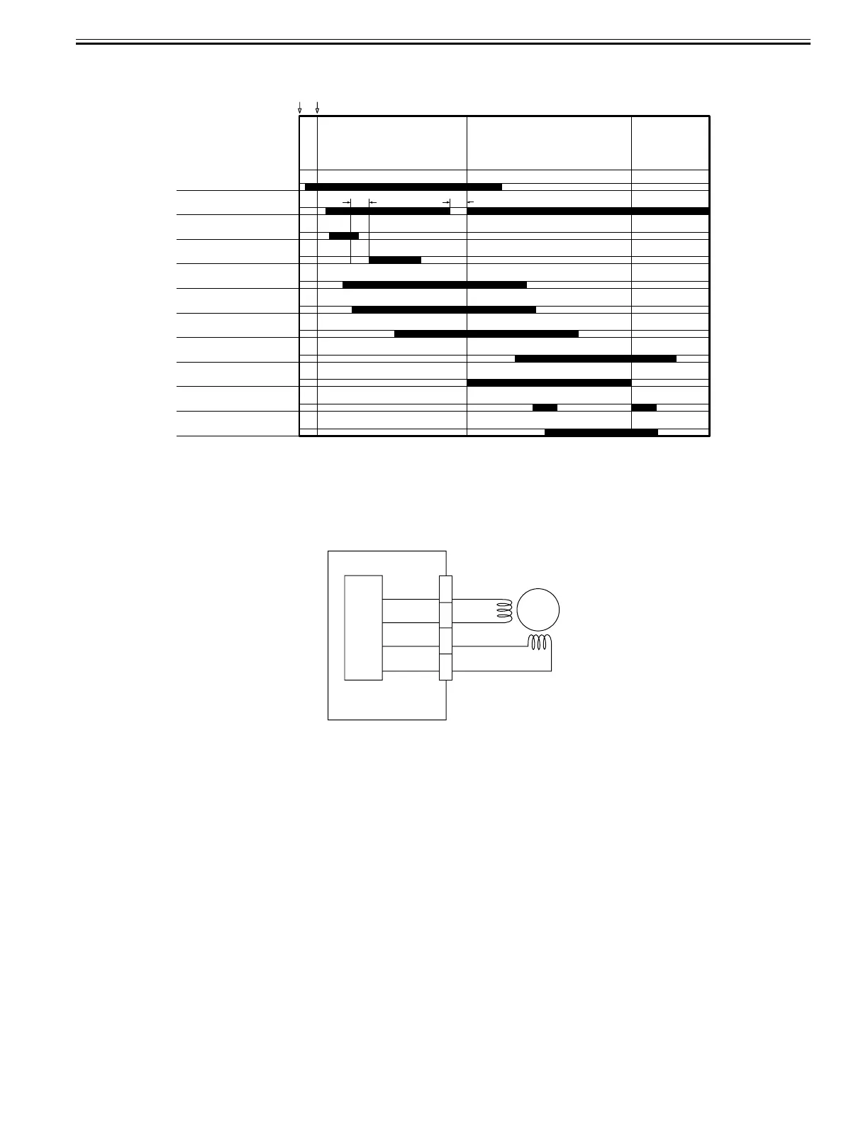
<Release operation sequence>
F-3-27
3.6.4 Release motor (M2) Control
0024-7002
The Release motor (M2) control circuit diagram is shown below. The Release motor (M2) is a 2-phase stepping motor. This circuit mainly performs the following
types of control:
- Motor ON/OFF control
- Motor rotation direction control
- Motor speed control
F-3-28
The Release motor of the ADF is controlled by the main controller PCB. The main controller PCB outputs drive pulses to the Release motor according to the doc-
ument feed timing.
The Release motor is a stepping motor. Its rotation direction and speed are controlled by changing the order of drive pulses (A, /A, B, /B) and frequency.
Release motor
(M2)
Release motor HP sensor
(SR11)
Original replacement
Start key ON
Document pickup signal input
Document reading
Document
separation/feed
Document
delivery
Read stanby
loop formation
Document set sensor
(SR5)
Delivery reversal sensor
(SR3)
Pickup/feed motor
(M1)
Pickup clutch
(CL1)
Timing sensor
(SR4)
Registration sensor
(SR1)
Registration clutch
(CL2)
Read sensor
(SR2)
Image leading edge signal
M2
1
2
3
4
J12
B
/B
/A
A
ADF driver PCB
Motor
driver
 Loading...