Chapter 4
4-2
3) Remove the pickup/feed motor [1] together with the support plate.
- Connector [2], 1 pc.
- Tension spring [3], 1 pc.
- Screw [4], 2 pcs.
F-4-5
4.3.2 Engaging Motor
4.3.2.1 Removing the Release Motor
0024-7013
1) Open the feeder cover.
2) Open the ADF.
3) Detach the front cover.
- Screw, 3 pcs.
4) Close the ADF.
5) Remove the release motor support plate [1].
- Connector [2], 2 pcs.
- Harness [3]
- Screw [4], 2 pcs.
- Harness guide [5]
- Screw [6], 3 pcs.
F-4-6
6) Remove the release motor [1].
- Screw [2], 2 pcs.
F-4-7
4.3.3 Timing Belt/Pulley
4.3.3.1 Removing the Timing Belt
0024-7014
1) Remove the ADF from the host machine.
- Screw, 2 pcs.
2) Open the feeder cover.
3) Detach the front cover.
- Screw, 3 pcs.
4) Remove the feeder cover.
- Screw, 1 pc.
- Positioning pin, 1 pc.
5) Remove the tray holder.
- Screw, 1 pc.
6) Move to the back of the host machine and detach the rear cover.
- Screw, 2 pcs.
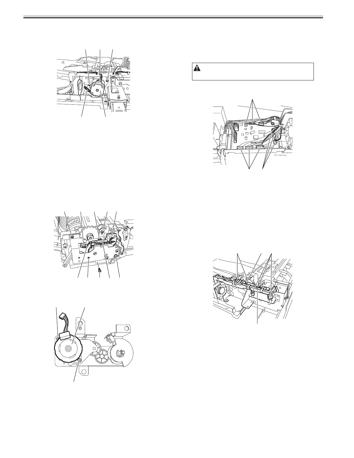
7) Disconnect the nine connectors [1] from the ADF driver PCB.
F-4-8
8) Remove the document tray.
- Screw
- Harness guide, 2 pcs.
- Document tray harness
9) Remove the pickup/feed motor together with the support plate.
- Connector, 1 pc.
- Tension spring, 1 pc.
- Screw, 2 pcs.
10) Remove the left hinge.
- Screw, 5 pcs.
11) Remove the harness guide [1].
- Connector [2], 5 pcs.
- Screw [3], 1 pc.
- Harness
F-4-9
12) Remove the pickup clutch/registration clutch support base.
- Screw, 2 pcs.
13) Remove the feed unit.
- Screw, 8 pcs.
[4]
[3]
[2] [4]
[1]
[2]
[4] [6]
[2]
[6]
[6] [4][1][3]
[5]
[1]
[2]
[2]
Remove the rear cover with the two claws released.
[1]
[1]
[1]
[2]
[1]
[3][2]