Chapter 4
4-14
5) Remove the tray holder [1].
- Screw [2]
F-4-57
6) Move to the back of the host machine and detach the rear cover.
- Screw, 2 pcs.
7) Remove the document tray [1].
- Screw [2]
- Harness guide [3], 2 pcs.
- Connector (J3)[4]
- Document tray harness
F-4-58
4.5 Electrical System
4.5.1 Fan
4.5.1.1 Removing the Fan
0024-7030
1) Open the feeder cover.
2) Move to the back of the host machine and detach the rear cover.
- Screw, 2 pcs.
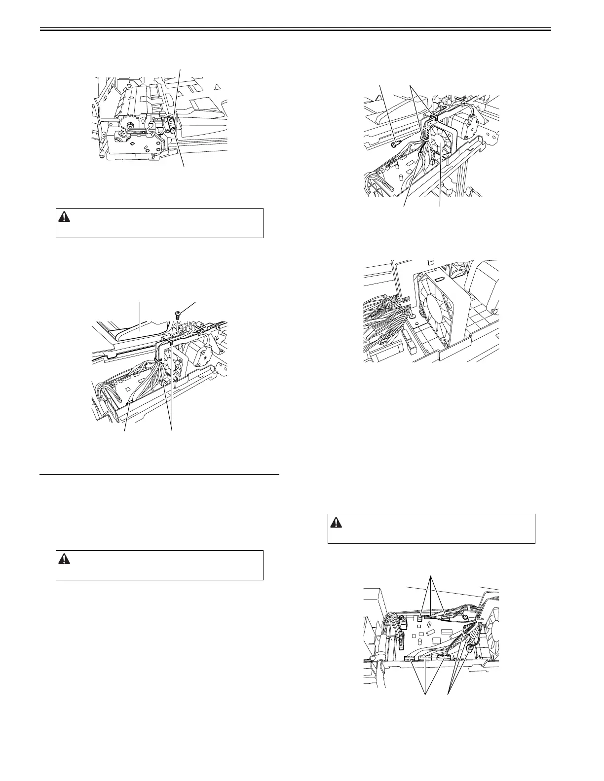
3) Remove the fan [1].
- Harness clamp [2], 2 pcs.
- Connector [3]
- Screw [4]
F-4-59
4.5.1.2 Precaution about Fan Installation
0024-7031
Install the fan with the arrow oriented as shown.
F-4-60
4.5.2 Inner Sensor of Feed Unit
4.5.2.1 Removing the Sensor in the Feed Unit
0024-7032
1) Remove the ADF from the host machine.
- Screw, 2 pcs.
2) Open the feeder cover.
3) Detach the front cover.
- Screw, 3 pcs.
4) Remove the feeder cover.
- Screw, 1 pc.
- Positioning pin, 1 pc.
5) Remove the tray holder.
- Screw, 1 pc.
6) Move to the back of the host machine and detach the rear cover.
- Screw, 2 pcs.
7) Disconnect the nine connectors [1] from the ADF driver PCB.
F-4-61
8) Remove the document tray.
- Screw
- Harness guide, 2 pcs.
Remove the rear cover with the two claws released.
Remove the rear cover with the two claws released.
[2]
[1]
[2]
[3]
[1]
[4]
Remove the rear cover with the two claws released.
[4]
[3]
[2]
[1]
[1]
[1]
[1]