Fixing System
Overview/Configuration
■ Overview
Fixing Delivery Assembly consists of the Fixing Assembly for fixing toner on the print paper and the Delivery Assembly for
delivering print paper on which toner is fixed to the Delivery Outlet (Face-down Tray).
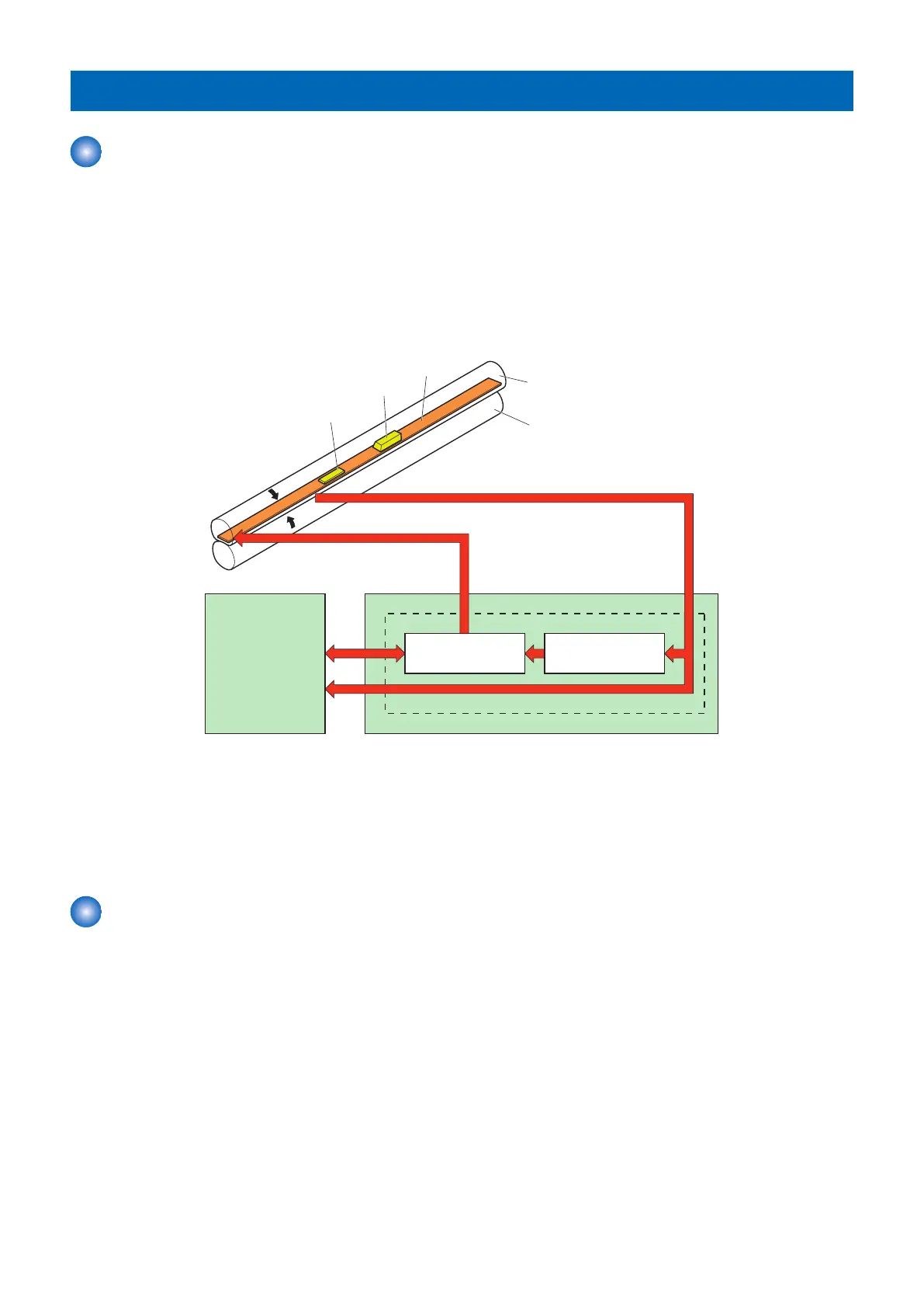
■ Main Parts in the Fixing Assembly
This circuit is for controlling the temperature of the Fixing Assembly.
The Fixing Assembly of this machine uses an on-demand fixing method, and consists of the following parts:
TH1
TP1
H1
Pressure roller
Fixing film
Fixing heater
safety circuit
DC controller
Low-voltage power supply unit
Fixing control circuit
FIXNG HEATER CONTROL signal
FIXING TEMPERATURE signal
Fixing heater
control circuit
• Fixing Heater (H1): Ceramic Heater for heating the Fixing Film
• Thermistor (TH1): Thermistor for detecting the fixing temperature. (Contact type)
• Thermoswitch (TP1): Thermoswitch for preventing the abnormal temperature rise of the Fixing Heater. (Contact type)
Temperature control of the Fixing Assembly which consists of these parts is performed by the Fixing Heater control circuit and
Fixing Heater safety circuit according to the command of the DC Controller.
Fixing Temperature Control
■ Heater Temperature Control
This control detects the surface temperature of the Fixing Heater and controls the drive signal of the Fixing Heater so that the
temperature of the Fixing Heater becomes the target temperature.
The temperature is detected by the Thermistor, and the DC Controller controls the temperature to become the target temperature
using the Fixing Heater drive (FSRD).
The following shows this control circuit:
2. Technical Explanation (Device)
33