Chapter 7
7-11
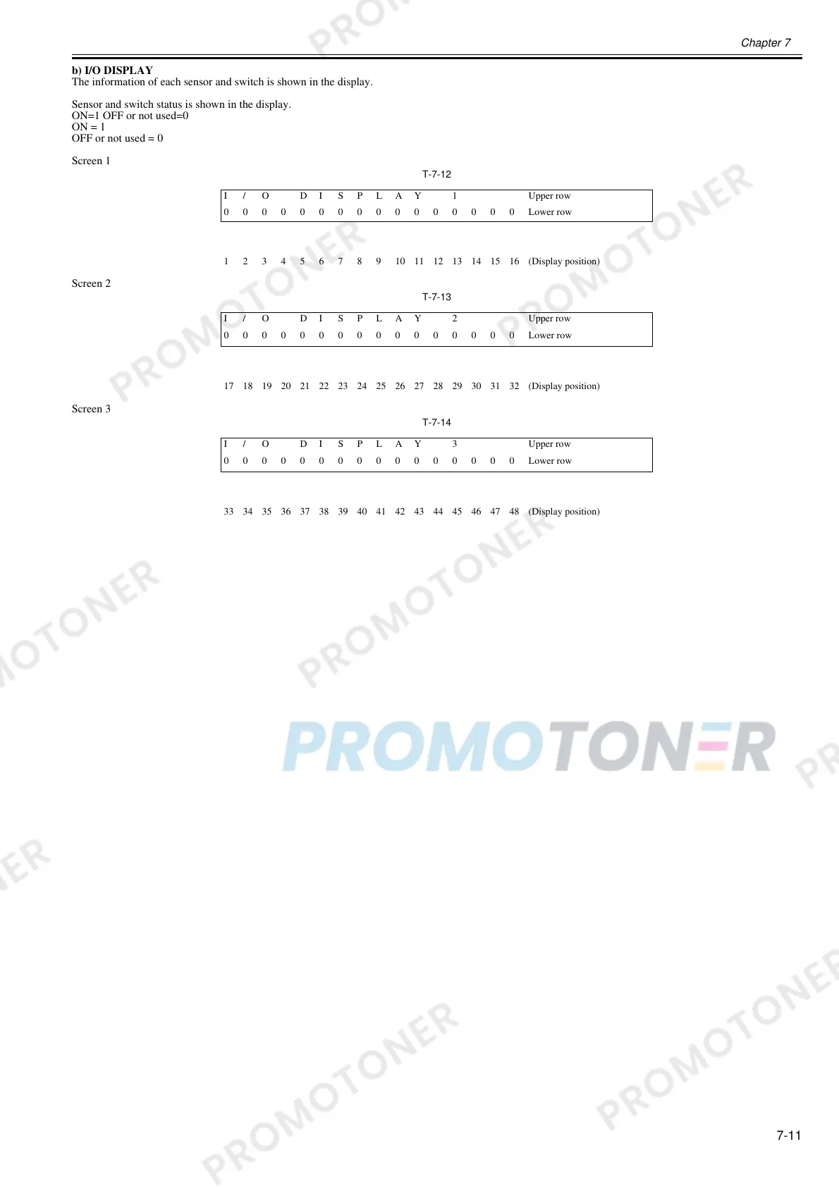
b) I/O DISPLAY
The information of each sensor and switch is shown in the display.
Sensor and switch status is shown in the display.
ON=1 OFF or not used=0
ON = 1
OFF or not used = 0
Screen 1
T-7-12
Screen 2
T-7-13
Screen 3
T-7-14
I / O D I S P L A Y 1 Upper row
0000000000000000Lower row
12345678910111213141516(Display position)
I / O D I S P L A Y 2 Upper row
0000000000000000Lower row
17 18 19 20 21 22 23 24 25 26 27 28 29 30 31 32 (Display position)
I / O D I S P L A Y 3 Upper row
0000000000000000Lower row
33 34 35 36 37 38 39 40 41 42 43 44 45 46 47 48 (Display position)
 Loading...