CHAPTER 8 ADF
COPYRIGHT
©
1999 CANON INC. CANON PC800s/900s REV.0 AUG. 1999 PRINTED IN JAPAN (IMPRIME AU JAPON)
8-33
E. Electrical System
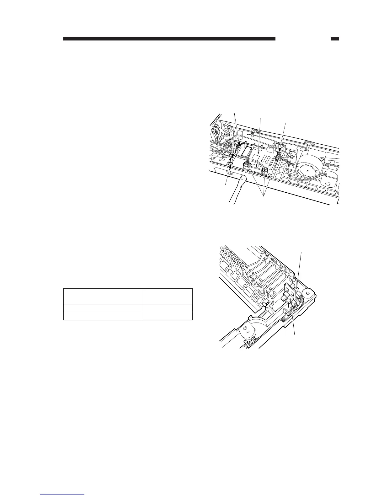
1. ADF Controller PCB
1) Remove the lower cover.
(See “B. External Covers.”)
2) Disconnect the five connectors [1], and
remove the two screws [2]; then, remove
the ADF controller PCB [3].
2. Original Placement Sensor and
Registration Paper Sensor
Pay attention to the colors of the cables
and connectors when connecting the connec-
tors of the original placement sensor and the
registration paper sensor.
Table 8-201
Figure 8-232
Figure 8-233