J
James ShermanSep 9, 2025
What does EEP.E2 mean on my CAS CI-100A, and how do I resolve it?
- AAlexis FarmerSep 9, 2025
If your CAS Accessories displays 'EEP.E2', it indicates that the USER parameter is not correctly set. Reset the items in USER.
What does EEP.E2 mean on my CAS CI-100A, and how do I resolve it?
If your CAS Accessories displays 'EEP.E2', it indicates that the USER parameter is not correctly set. Reset the items in USER.
How to display weight in the desired unit on my CAS Accessories?
If your CAS Accessories cannot display the weight in the desired weighing unit, the unit may not be enabled in the settings, or d?5oz,when unit is lb:oz. Enable the unit in CONFIG-UNITS.
What does PWT.ER mean on my CAS Accessories, and how do I fix it?
If your CAS Accessories displays 'PWT.ER', it indicates that the piece weight is erroneous because it’s too small (less than 0.5d), or the weight on the platform is too small to define a valid reference weight. Use a greater weight for the sample.
What does PCT.ER mean on my CAS CI-100A and how can I resolve it?
If your CAS Accessories shows 'PCT.ER', it means the Unit-Percentage -Weight is erroneous because it’s too small (the weight of 1%, 0.1%, or 0.01% determined by CONFIG-FUNC-PERCNT is less than 0.5d). Use a greater weight for the sample.
What does CACU.ER mean on my CAS Accessories, and what should I do?
If your CAS Accessories displays 'CACU.ER', it means there was an internal calculation overflow. Adjust the value of the PWT or PCT.
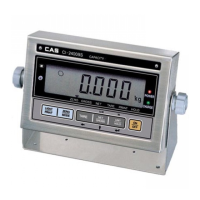
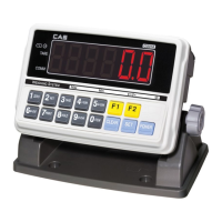
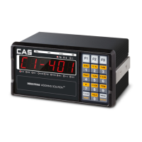
Details the physical outline and bracket installation for the CI-100A indicator.
Covers power options, display specs, and environmental operating conditions.
Details load cell excitation parameters and serial/Bluetooth communication options.
Covers analog circuit, accuracy, capacity, and division settings.
Describes calibration methods and the optional real-time clock.
Lists various additional functions like zero range, tare, and hold.
Explains the meaning of various symbols and indicators displayed on the faceplate.
Details the functions of the HOLD/SETUP key in different modes.
Explains the functions of the PRINT/FUNC key in various modes.
Describes the functions of the ACC/TOTAL key in different modes.
Outlines the functions of the UNIT/DATA key in different modes.
Details the functions of the TARE/PRESET key in different modes.
Explains the functions of the ZERO/ON/OFF key in various modes.
Shows the main menu structure with CONFIG, USER, CAL, MISC, TEST, and BT options.
Details the sub-menu options under CONFIG, including REGULA, PRIM.N, PRIM.D.
Continues detailing CONFIG submenu options like PRIM.Ut, SECND.N, MOTION, UNITS, ZRO.PNT.
Continues detailing CONFIG submenu options like FILTER and FUNC.
Describes resetting user parameters and configuring COM1 and OUT1 settings.
Continues USER submenu options for COM2, covering various data outputs.
Continues USER submenu options for COM2 (cont.) and COM3, including BEEP, COMPAR, HOLD.
Continues USER submenu options for COM3, covering various data outputs.
Continues USER submenu options for COM3 (cont.) and HOLD modes.
Continues USER submenu options for OTHER settings like AVG.TIM, CMD.SRC, OFF.MD.
Controls calibration status, performs zero, linear, and geographical adjustments.
Accesses MISC options (code, voltage, time, version) and performs TEST functions.
Guides Bluetooth setup, communication settings, device management, and version check.
Covers key functions, changing modes, and entering HOLD.
Details scale power, zeroing, and tare operations.
Outlines limitations for ZERO and TARE operations based on standard and weight.
Describes how to output data using the PRINT key.
Explains how to accumulate weight, pieces, or percentage.
Describes how to select different weight units.
Explains weighing goods, counting, and enabling the function.
Details methods to obtain piece weight via keypad or sample weighing.
Explains setting up and using the count comparison function.
Details how to input piece weight using the keypad.
Describes how to obtain piece weight by weighing known samples.
Explains weighing goods and displaying percentage, and mode entry.
Explains inputting weight/percentage or weighing known percentage samples.
Explains setting up and using the percentage comparison function.
Details how to input weight and percentage from the keypad.
Describes how to weigh samples with a known percentage.
Details enabling, entering, and operating the BMI working mode.
Explains how to select between displaying weight or BMI.
Describes indicator behavior when net weight is below a certain threshold.
Explains HOLD function purpose and how to enable it.
Describes entering HOLD mode and lists different HOLD types.
Explains Positive Peak, Negative Peak, and Toggle HOLD modes.
Explains Average HOLD and Auto HOLD modes.
Explains the meaning of the HOLD annunciator status.
Explains the function, how to enable it, and set comparison limits.
Describes how results are indicated and where to find more information.
Explains the accumulation function and how to enable it (MANUAL/AUTO).
Explains manual and automatic accumulation procedures.
Describes how to view accumulated times and total.
Guides on entering calibration mode and lists options like zero and linear.
Details the steps for linear calibration points CAL.P0 to CAL.P3.
Covers geographical adjustment and input/viewing calibration parameters.
Describes the end of calibration and indicator restart.
Explains how to enter and adjust displayed weight using fine-tune.
Details methods to remove the effect of the weight fine-tune ratio.
Explains examining ADC output stability and entering the mode.
Details setting reference zero, displaying codes, and selecting filters.
Details checking and calibrating battery and regulated voltage.
Guides on accessing and exiting voltage display/calibration modes.
Covers accessing, displaying, and modifying the current time.
Describes how to exit the time view/setting mode.
Covers accessing, displaying, and modifying the current date.
Describes how to exit the date view/setting mode.
Covers accessing, displaying, and exiting the firmware version information.
Guides on entering, performing, and exiting the display test mode.
Guides on entering, performing, and exiting the keyboard test mode.
Details test setup, entry, data display, and exit for receiving tests.
Details test setup, entry, data modification, and exit for transmitting tests.
Covers COM ports, baud rate, byte format, and string item lengths.
Explains symbols and communication details for SINGLE layout.
Lists commands and responses for SINGLE layout.
Details EH-SCP, SCP-12 protocols and provides layout examples.
Provides an overview of the PCB connectors and jumpers.
Details pinouts and electrical levels for key power/load connectors.
Details serial/USB connectors and jumper functions.
Explains the meaning of various symbols used in the indicator.
Provides common issues, causes, and remedies for indicator problems.
Shows the mapping of ASCII characters to their LCD/LED display representation.
Lists the items included in the product package and their quantities.
Details the version history of the indicator and manual updates.
| Brand | CAS |
|---|---|
| Model | CI-100A |
| Category | Accessories |
| Language | English |