11
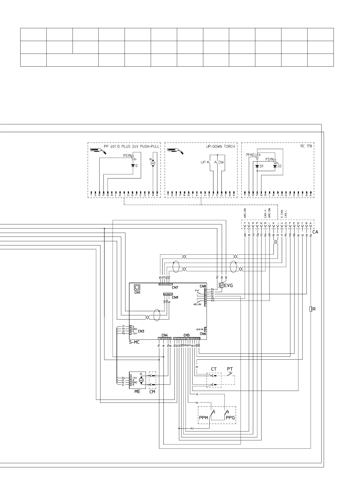
KEY TO THE ELECTRICAL DIAGRAM
•1 •2 •3 •4 •5 •6 •7 •8 •9 •10 •11 •12
C C2 CA CHR CM Cp CT D2 EVG F-EMC IL L2
•13 •14 •15 •16 •17 •18 •19 •20 •21 •22 •23 •24
ME MIH MIL MV1-2 P1 P2 PPG PPM PT R R2 RP
•25 •26 •27 •28 •29 •30 •31 •32 •33 •34
RS S-INT DIG S-INV S-LINK S-MC S-PS TA TH2 TP VR
•1 Capacitor •2 SNUBBER capacitor for output diodes •3 17 pin connector for remote control connections •4 Cooling system power connector •5 Drive
motor connector •6 Quick connection protection capacitor •7 Torch connector •8 Secondary diode •9 Gas solenoid valve •10 EMC filter •11 Power supply
switch •12 Secondary inductor •13 Drive motor with encoder •14 Primary upper IGBT module •15 Lower primary IGBT module •16 Fan motor •17 Main
primary transformer (start) •18 Main primary transformer (end) •19 Gas testing button •20 Motor testing button •21 Torch button •22 Resistor •23 Output
diode snubber resistor •24 Primary rectifier •25 Secondary rectifier •26 Digital interface PCB •27 Inverter PCB •28 Capacitors PCB •29 Motor control PCB
•30 Power Source PCB •31 Hall effect transformer •32 Secondary thermostat •33 Main transformer •34 Output diodes snubber varistor
2101AA87