17
GB
INSTALLATION
RX DC X-RAY UNIT
Figure F
Figure G
Figure F
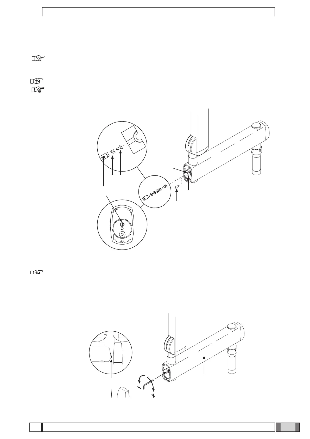
• Take the grubscrew used to stop rotation (o) from the x-ray unit kit and tighten it at point H (tighten it fully and then
loosen by ½ turn).
NOTE:Turn the pantograph arm to check that the adjustment has been made properly.
Take the clutch assembly (friction element, screw and 4 curved washers) from the x-ray unit kit and install it
at point L.
NOTE: Insert the curved washers (j) and the friction element (k) as indicated in gure F.
NOTE: The friction element (k) can be placed in the correct position (vertical cut) by inserting a screwdriver
in the hole provided for the screw (n).
Figure G
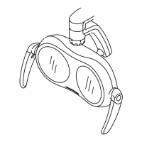
• Adjust the clutch which has just been installed.
NOTE:Turn the pantograph arm during the adjustment to check that the clutch is providing the correct
amount of friction.
• Install the plugs (p) on the extension arm (c).
• Attach the adhesive bumper (q) (supplied in the kit) in the centre of the plug at the point indicated in the diagram.