32
GB
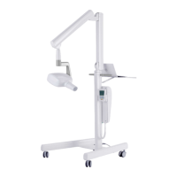
INSTALLATION
RX DC X-RAY UNIT
ARCH TECHNOLOGY
NOTE: This section applies only to models RX DC REF: MRXU*****
(Character * can be any alphanumeric value)
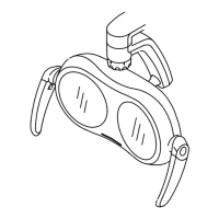
In the versions equipped with arch technology, the X-ray head can freely rotate on both
its horizontal and vertical axis.
Simply moving the X-ray head allows positioning it at the desired angle to perform the
exposure.
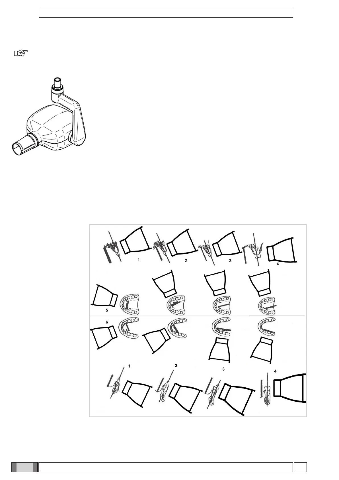
6.9 Position of the x-ray plate or sensor
The parallel technique, where applicable, provides more accurate images in terms of size compared to the bisecting
technique. A rectangular collimator, with 30 cm (12"), focus-skin distance, is always preferable to obtain better quality
pictures. To avoid exposing the image receiver only partly (whether it is a sensor or photostimulable phosphorus plate
system) an alignment device that gives rectangular collimators guidelines should be used. These lines are usually
given on the alignment ring.
• Parallel technique.
1 Incisors
2 Canines
3 Premolars
4 Molars
5 Upper arch
6 Lower arch
The x ray emission axis is perpendicular to the image receiver (for example a sensor or photostimulated phosphor
plate) which in turn is parallel with the tooth’s long axis.
• As a result, the picture of the tooth will only be deformed by the divergence of the x rays in relation to the focus spot.