Do you have a question about the CEFLA RX DC and is the answer not in the manual?
Introduction to the manual and the manufacturer.
Guidelines to prevent hazardous situations and ensure safe operation of the equipment.
Details the dimensions and included components of the X-ray unit packages.
Instructions for proper handling and storage conditions of the packaged unit.
Specifies required temperature, humidity, and pressure for installation.
Requirements for wall mounting, including fixing systems and anchorages.
Details central control unit power supply specifications and electrical wiring compliance.
Connecting the central control unit and generator light for operation.
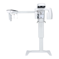
Guidance on correctly positioning the X-ray unit's main structure on the wall-mount plate.
Instructions for installing the wall-mounted plate, including various stud types.
Steps for installing the extension arm, including specific PASS THROUGH models.
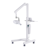
Procedure for assembling and installing the mobile trolley unit.
Guidance on connecting and installing the double pantograph arm assembly.
Installing the RX DC generator with 'ball end socket' or standard joint.
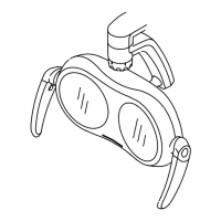
Steps for attaching the collimator to the X-ray generator.
Balancing and adjusting end-stops for the double pantograph arm.
Wiring connections and completion of wall-mounting plate and handheld holder.
Procedure for powering on the X-ray unit and initiating its operational test sequence.
Details on wireless/wired handheld operation, modes, and battery status.
Explanation of icons and indicators displayed on the handheld control unit.
How to use the function keys and emission key on the handheld for exposure control.
Managing unit stand-by time and verifying operational parameters before exposure.
Summary of the default factory settings for the X-ray unit's operation.
Guidance on aligning the X-ray head with the image receiver for optimal imaging.
Techniques and considerations for positioning the X-ray plate or sensor for image acquisition.
Step-by-step guide for performing an X-ray exposure using the handheld unit.
Guides on using key combinations to access and modify settings and menus.
Setting the safety unlock mode for the ball joint to prevent accidental movement.
Choosing between AUTO, USER, or specific KV/mA modes for X-ray operation.
Selecting the correct type of removable cone for optimal X-ray unit performance.
Procedure for calibrating the X-ray head, involving multiple exposure shots.
Details of the Power Board and its diagnostic LED indicators for troubleshooting.
Information on the X-ray Head Control Board, connectors, and DIP switch settings.
Step-by-step guide for replacing the X-ray head control card, including calibration notes.
Instructions for removing and replacing the X-ray head, including serial number sticker.
Procedure for associating the handheld unit with the X-ray head after replacement.
Setting the X-ray head to combination mode and sending the recognition signal.
Procedures for inspecting and modifying Wi-Fi settings and troubleshooting interference.
Instructions for replacing the SLIP RING assembly on specific RX DC models.
Comprehensive list of handheld error codes, their types, descriptions, and troubleshooting steps.
Detailed electrical wiring diagrams for various RX DC unit reference models.
Annual inspection checklist and procedures for ensuring operational safety and reliability.
| Generator Type | High Frequency |
|---|---|
| Technology | Digital |
| Sensor Type | CMOS Sensor |
| Voltage Range | 60 to 70 kV |
| Current Range | 4 mA, 7 mA |