23
K5
K2
K3
230V
115V
K1
K6
K15
GB
INSTALLATION
RX DC X-RAY UNIT
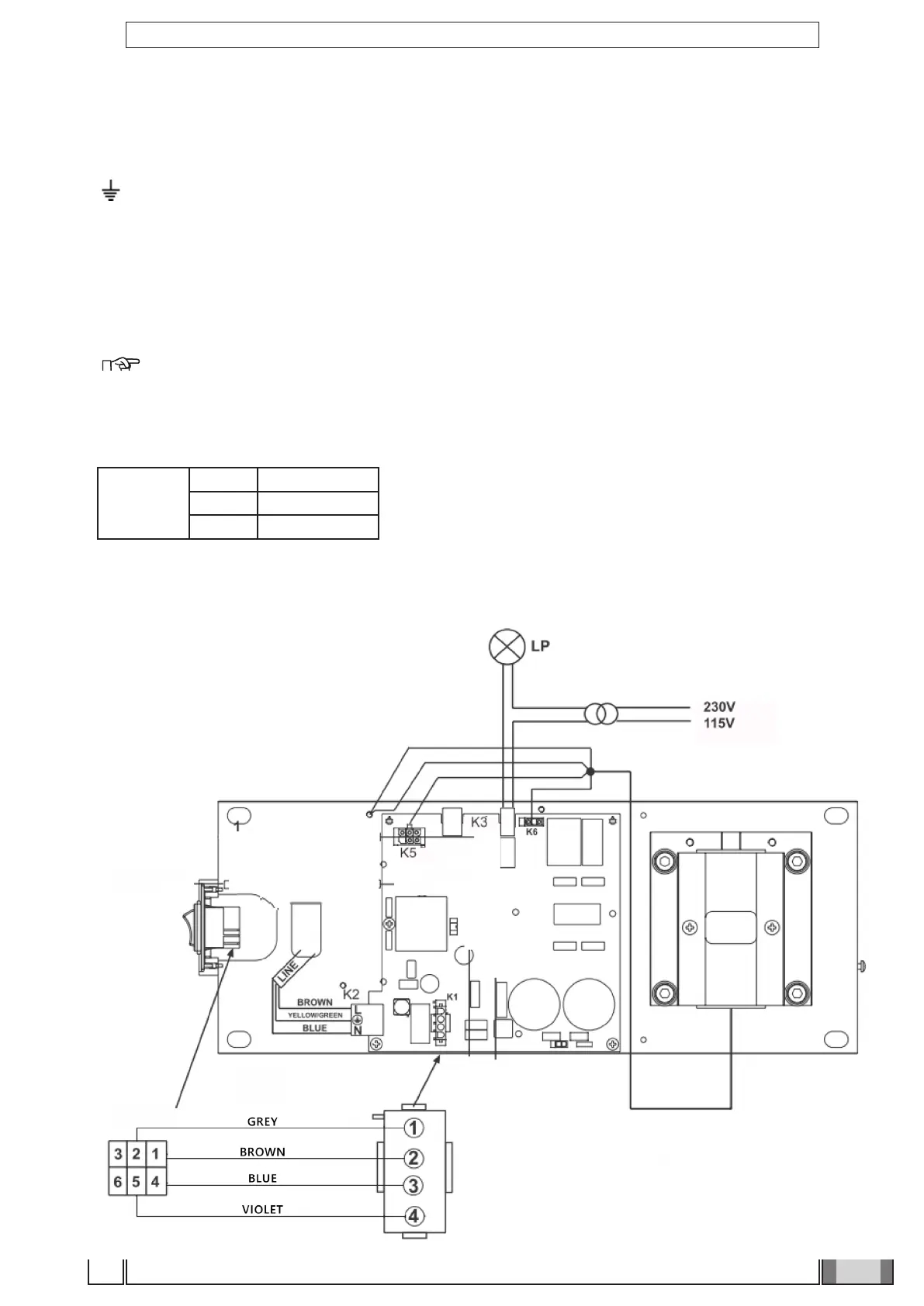
4.11 Wall-mounted plate wiring connections
• Connect the power cable (LINE) to terminal K2, observing the following positions:
L - SUPPLY (BROWN WIRE)
- GROUND (YELLOW/GREEN wire)
N - NEUTRAL (BLUE wire)
• Connect the generator’s power cable to the respective connectors, observing the following positions:
K6 - brown wire and blue wire.
K5 - white wire – black wire – red wire – green wire – purple wire.
Eyelet connectors - Both found near the card (see gure S).
NOTE: Place the excess cable under the card.
• If an external "ready" indicator light is installed, connect the 2 light control (LP) wires (0.5 mm cross-section) to
connector K3;
• If INTERLOCK is installed, connect the 2 wires (0.5 mm cross-section) to connector K18, otherwise short-circuit it;
• In case of handheld unit with wire, connect it to K15.
K15
PIN 1 Red
PIN 2 White / Brown
PIN 3 Blue
4.12 Completion of wall-mounting plate and holder for handheld.
Figure S